| Search | Login/Register
   Home » Analog Playback» The last phonocorrector: “End of Life" Phonostage (311 posts, 15 pages)
  Print Thread | 1st Post |  
Page 6 of 16 (311 items) Select Pages:  « First ... « 4 5 6 7 8 » ... Last »
   Target    Threads for related reading   Most recent post in related threads   Forum  Replies   Views   Started 
  »  New  Where are our good phonostages?..  Omnigon Tubes...  Analog Playback Forum     61  638407  05-31-2004
  »  New  The Expressive Technologies SU-1..  “too bright” or “resolution” or “details” with SUT prim...  Analog Playback Forum     33  361525  12-30-2004
  »  New  EAR 834P Modification Guide..  The cap will not change volume in the pass band...  Analog Playback Forum     45  615949  02-09-2006
  »  New  My Analog Playback: the fat lady has sung..  My analog setup update....  Analog Playback Forum     9  115160  04-04-2006
  »  New  Phono stages with SU-1..  SU-1...  Analog Playback Forum     4  63752  11-23-2007
  »  New  Chasing utopian better phono interconnect...  Did I miss something?...  Analog Playback Forum     6  106898  06-05-2008
  »  New  Buying a last cartridge...  Lucky you...  Analog Playback Forum     80  779385  09-05-2008
  »  New  EAR 834P mods..  The cap will not change volume in the pass band...  Analog Playback Forum     45  615949  11-04-2008
  »  New  AMR PH-77: just another phonostage or more?..  Oh, yeah... the sound of the Thing Itself......  Analog Playback Forum     11  126922  07-05-2009
  »  New  An interesting Russian pnonocorrector...  Uber-tweeky phono topologies deconstructed...  Analog Playback Forum     9  95071  03-01-2010
  »  New  Expressive Technologies SU-1 and cartridge output and i..  MV and Ohms...  Analog Playback Forum     2  31925  07-07-2011
  »  New  How to run MM-type cartridge into MC phonostage?..  Quite interesting....  Analog Playback Forum     6  64081  11-13-2011
  »  New  The tales of two phonostages: Allnic and 834PT...  The tales of two phonostages: Allnic and 834PT....  Analog Playback Forum     0  22391  12-21-2011
08-30-2011 Post does not mapped to Knowledge Tree
Paul S
San Diego, California, USA
Posts 2,570
Joined on 10-12-2006

Post #: 101
Post ID: 16888
Reply to: 16887
What, No Breadboard?
fiogf49gjkf0d
Nice looking unit, N-set.  I also go out of my way to use part leads only in lieu of extra wire whenever possible.  I really don't care what it "looks like" on this score.  At least your wires are all nicely dressed.  You will find out soon enough if they are "properly" routed.

May I ass-u-me that the electrolytics that appear to be lying down on the Cu ground plane are actually raised up on some sort of di-electric stick-um?  And what are the little "blocks" on some of the BlackGates?  "Dampers"?  Have you tried fine Cu screen instead of plate in thermally-challenged areas?

You have probably already heard this before, but for PS chokes, the better Hammond are not only reasonably priced and easy to get, but they are consistently silent.

Good luck with early trials.  I always figure I'm ahead if it doesn't blow a fuse or a tube, and/or simply melt down the first time I flip the switch...

Air caps appear to be un-warped...

God...  we sound like (gasp...)  DIY'ers!

Best regards,
Paul S
08-30-2011 Post does not mapped to Knowledge Tree
N-set
Gdansk, Poland
Posts 609
Joined on 01-07-2006

Post #: 102
Post ID: 16889
Reply to: 16888
Don't laugh too loud...
fiogf49gjkf0d
...this is my first serious attempt to pack something into a case.

 Paul S wrote:
Nice looking unit, N-set.  I also go out of my way to use part leads only in lieu of extra wire whenever possible.  I really don't care what it "looks like" on this score.  At least your wires are all nicely dressed.  You will find out soon enough if they are "properly" routed.


Thanks for kind words. I've been already listening to the noise it produces. On my Stas SR007 headphones,
full volume it's quite acceptable white noisecomming most probably from the input tube's thermal noise (I've been using cheap Chinese 12AX7 for the testing). More carefull test do show some 50Hz enviromental pick-up present in one of the channels. My (uncalibrated)
HP400F shows around 16mV noise with both the PSU and signal blocks without covers.

 Paul S wrote:

May I ass-u-me that the electrolytics that appear to be lying down on the Cu ground plane are actually raised up on some sort of di-electric stick-um?  And what are the little "blocks" on some of the BlackGates?  "Dampers"?  Have you tried fine Cu screen instead of plate in thermally-challenged areas?


No Black Gates here Paul! These are Elna Cerafines. The "blocks" are silicone-glued sorbothane restsovers for imaginative damping.
If you find it stupid, I'd probably agree with you. The caps are lifted above the Cu plane without any insulation exepct for the air
(why create additional caps using additional insulators?), but that's not critical I guess--one of the
legs is grounded anyway. I've lifted them mostly because the plate gets warm from the tubes and regulator IC's.
Actually, this is not visible but it took me quite some time and effort to bend and place all the parts/leads
in such a way that they do not touch each other and if possible cross at 90deg (with obviously some exceptions where it was not possible)
Not exactly understand what you mean by the Cu screen and in which areas? At this side of the chassis nothing gets really hot, the hottest
are the tubes at the other side.

 Paul S wrote:

You have probably already heard this before, but for PS chokes, the better Hammond are not only reasonably priced and easy to get, but they are consistently silent.


The noise not the problem here--my HV tranny is the noisest thing here, but still not annoying (you hear it from 0.5m without the cover,
which will be damped with a heavy rubber). I've used a better Hammong at the HV entry because of it's higher voltage rating
(and also secondarily to prevent buzz at it sees around 700Vp-p or something like that).


 Paul S wrote:

God...  we sound like (gasp...)  DIY'ers!


Shit...


Cheers,
Jarek
STACORE
08-30-2011 Post does not mapped to Knowledge Tree
Romy the Cat


Boston, MA
Posts 10,049
Joined on 05-28-2004

Post #: 103
Post ID: 16890
Reply to: 16887
So far it is good.
fiogf49gjkf0d
I do like the assembly. I o not fine it messy at all BTW. I would like to have inputs slightly closer to the grid of the first tube. I would also run the heater wire further from the circuit and decent them from higher distance. With all in place you shall have sun 3-5mV of notice from MC level. BTW, I do not see any MC level efforts, so I guess it will be juts MM phonostage, right? Make sure that your input chokes “work” and that you bled enough current. Use good tubes and post your observations about Sound. BTW, you might want to make observations by replacing the air caps with mica caps (or whatever best caps you will be able to find). It is very easy to do and the results are very illustrative.  Also, after you calibrated the air caps do not shake the unit as the air caps might move. It is difficult to adjust the air caps after they are in circuit…

The Cat

PS: I did purge the image gallery.


"I wish I could score everything for horns." - Richard Wagner. "Our writing equipment takes part in the forming of our thoughts." - Friedrich Nietzsche
08-30-2011 Post does not mapped to Knowledge Tree
Paul S
San Diego, California, USA
Posts 2,570
Joined on 10-12-2006

Post #: 104
Post ID: 16891
Reply to: 16889
Your 50 is my 60 (buzz-kill)
fiogf49gjkf0d
No way to guess about grounding, at least until you show the final traces.  I simply must use shielded inputs, and I bleed these "upstream" via a "dedicated" ground (and certainly NOT the "house ground"...).  Yes, I realize this is not the desired "star" grounding.  However, it was this or madness.  Also, some units require to cap any and all unused inputs, and some even the unused outputs.

BTW, I would root out that ".5m" buzz like a terrier on speed...

Best regards,
Paul S
08-31-2011 Post does not mapped to Knowledge Tree
N-set
Gdansk, Poland
Posts 609
Joined on 01-07-2006

Post #: 105
Post ID: 16893
Reply to: 16890
The assembly and the buzz
fiogf49gjkf0d
 Romy the Cat wrote:
I do like the assembly. I o not fine it messy at all BTW. I would like to have inputs slightly closer to the grid of the first tube..

I'd prefer to have the ground terminals much closer to the ground plane and more of them (like in your layout, but not
using steel/copper contact, rather copper/copper like I did). The signal layout has been compromised by the
CCS heating elements, which, perhps not very wisely, I've decided to mount directly on the tube sockets. If doing it the 2nd time, I'd put the CCS somewhere close to the cap bank (on the right on the pic's). The input to the grid--I wanted to have quite some
space for the SUT's and eventual future experimentation with multiple inputs and ways to switch them
(thermocouple-grade, microvolt -rated Hg relais).
 Romy the Cat wrote:
I would also run the heater wire further from the circuit and decent them from higher distance.

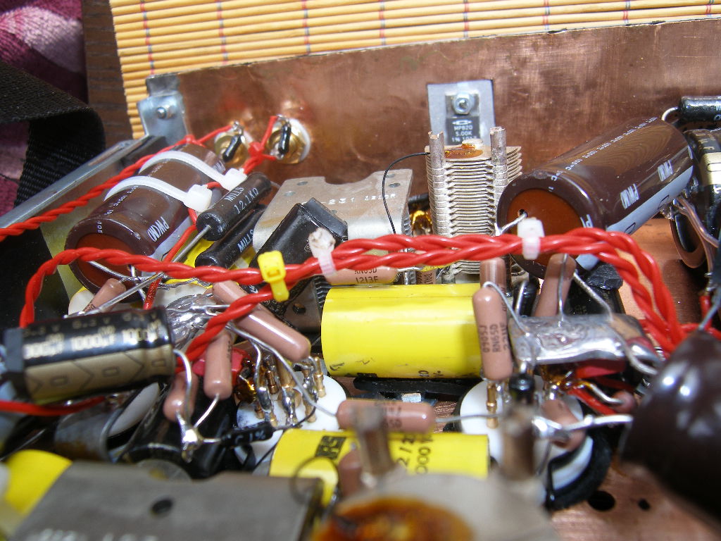
Yes, it was one of the fuck-ups--a bit too short heater wires. But they do not lie on the parts as the pics suggest,
they are a bit elevated:
Heaters.JPG
 
 Romy the Cat wrote:
With all in place you shall have sun 3-5mV of notice from MC level. BTW, I do not see any MC level efforts, so I guess it will be juts MM phonostage, right?

No! You've named that very well--"MC efforts". It has been an ongoing, half-a-year effort to get any output from
Tribute and I begin to loose hope honestly. Pieter is a nice-sounding guy, but he is either very very slow
or not interested and pushing the order to the end of his list. I wanted to experiment with HUGE custom nanocrystaline
cores, which I've sent him back in april. The cores turned out not too efficient induction-wise, but I insisted
to wind them anyway, hoping induction is not the only parameter here and promissed to buy his regular SUT's
if the experiment fails. So far no sensible output. If someone has any interesting option for SUT's I may be interested.
 Romy the Cat wrote:
Make sure that your input chokes “work” and that you bled enough current. Use good tubes and post your observations about Sound. BTW, you might want to make observations by replacing the air caps with mica caps (or whatever best caps you will be able to find). It is very easy to do and the results are very illustrative.  Also, after you calibrated the air caps do not shake the unit as the air caps might move. It is difficult to adjust the air caps after they are in circuit…

I'll scope the PSU soon to check the opreation. Caps, ok, I cantry that. Adjusting the caps--this battle is stillin front of me.
Actually my plan was to adjust them in the circuit,  rather than desolder-adjust-resolder.
 Romy the Cat wrote:
PS: I did purge the image gallery.

(whatever) god bless you!!!
 Paul S wrote:
No way to guess about grounding, at least until you show the final traces.  I simply must use shielded inputs, and I bleed these "upstream" via a "dedicated" ground (and certainly NOT the "house ground"...).  Yes, I realize this is not the desired "star" grounding.  However, it was this or madness.  Also, some units require to cap any and all unused inputs, and some even the unused outputs.

BTW, I would root out that ".5m" buzz like a terrier on speed...

Paul, the output noise I've been having so far is not a buzz but a white noise,
which I attribute to shitty, noisy tubes (and eventually VR's, I'll put a screening cans around them).
I'll try to record and show the traces.
One channel (the one "down" on the picture, farthest from the output RCA's) do have
a very faint feeling of the 50Hz buzz. It's below my level of audibility, I more "feel it"
with my headphones max vol (or see on the scope) rather than hear.
It dissappears when I touch either the case, which suggest some grounding probelm...very strange...
If I lift the ground (break Cu ground plane connection to the case) the buzz becomes
very loud, but only in this one channel. The other is intact. I'll have to investigate that.
Both channels are wired in a similar way, the heaters are DC, well stabilized, etc.


Cheers,
Jarek
STACORE
08-31-2011 Post does not mapped to Knowledge Tree
Romy the Cat


Boston, MA
Posts 10,049
Joined on 05-28-2004

Post #: 106
Post ID: 16894
Reply to: 16893
Make sure that your LC filtration works properly.
fiogf49gjkf0d
 N-set wrote:
I'll scope the PSU soon to check the opreation. Caps, ok, I cantry that. Adjusting the caps--this battle is stillin front of me. Actually my plan was to adjust them in the circuit,  rather than desolder-adjust-resolder.
 Adjusting caps in LC filtration is irrelevant. In LC filtration the subject of your concern shell be not capacitance but the inductance. You do not run frequency specific circuit on B+ side and to you it shell be near irrelevant what lowest frequency of AC your power caps will shunt to ground. In contrary you would like to make sure that your choked have critical inductance and that you drown enough current with your bleeders. I would say that the whole idea of using the LC for this corrector on B+ side a bit questionable as the tube drown 2-3mA and a regular caps will be just fine. Still my love to LC took over all my rational.  So, circulate or measure that your chokes, in filaments and in B+ side both operate properly. LC filtration is way advance ONLY if the chokes works properly. 
 
The Cat


"I wish I could score everything for horns." - Richard Wagner. "Our writing equipment takes part in the forming of our thoughts." - Friedrich Nietzsche
08-31-2011 Post does not mapped to Knowledge Tree
N-set
Gdansk, Poland
Posts 609
Joined on 01-07-2006

Post #: 107
Post ID: 16895
Reply to: 16894
Caps and chokes
fiogf49gjkf0d
Oh, Romy, I meant the air caps in the corrector loop of course!!!
Adjusting PS caps I leave to AA morons and alike.

Believe me or not I did go very serious about the proper choke input operation.
What I meant is that I have to get hold of a scope to check if it all works as it should.
The input chokes were already changed once (once too low voltage rating,
another time too low inductance for a given voltage/current).
The heater/bias input choke is for example 300mH (!), dictated by the tranny
output voltage/heater current (and the Hammond range). Then the LC tanks are additionally damped
with series resistors to bring the Q's down. I'll post the schematics.

I'd strongly desagree that the L-input on B+ is questionable. First of all the choke is dictated
by both the input voltage and the current draw. It's perfectly fine to make a 2mA choke input
supply--the choke will have to have a big inductance, which is easy with low mA's.
Second there are VR's and a serious bleeding resistor down the chain so a small current
drawn by the signal part itself is not an issue. I very much like this implementation of yours. I believe
it helps a lot to stabilize the supply.
Third, and probably most important, L-input is inherently less noisy (provided min current is
met). With such a delicate preamp, the current spikes
emitted by the cap input filter (they depend on the cap size, not the current draw, and could easily go into ampere's range
if the cap is big enough...which would be the case to filter well) could do a lot of harm: may spread all over
the place and trigger ringing  here and there. I'd not even consider a C-input.


Cheers,
Jarek
STACORE
08-31-2011 Post does not mapped to Knowledge Tree
oxric
Posts 194
Joined on 02-12-2010

Post #: 108
Post ID: 16896
Reply to: 16895
The price of fame
fiogf49gjkf0d
N-Set,

I have a similar experience as yours when it comes to Peter of Tribute Audio. One moment he is all enthusiastic and the next moment he stops all communication. I think this might be the unfortunate price of fame and success.

By the way, is there a chance you could send me an email at my email address at rakeshpoorun@gmail.com as I have a query for you?

Best regards
Rakesh
08-31-2011 Post does not mapped to Knowledge Tree
N-set
Gdansk, Poland
Posts 609
Joined on 01-07-2006

Post #: 109
Post ID: 16897
Reply to: 16896
Tribute
fiogf49gjkf0d
 oxric wrote:
N-Set,

I have a similar experience as yours when it comes to Peter of Tribute Audio. One moment he is all enthusiastic and the next moment he stops all communication. I think this might be the unfortunate price of fame and success.

By the way, is there a chance you could send me an email at my email address at rakeshpoorun@gmail.com as I have a query for you?

Best regards
Rakesh


I don't think it's fame. I've spoken to him several times. He sounds everything but a
celebrity. The explanation that I have is as follows:

1) He works alone, winding all those kilometers of wire just himself; he manages the business
himself, no distributors etc. He becomes enthusiastic at the beginning, perhaps promisses too
much and then recalculates the forces and calms down..without a notice (living a short period
of my life in Amsterdam, it's not the first time I experience such a behavioiur)

2) My quest is not interesting to him as he mainly looks at how to get the max inductance out
of the core and my cores, to my unpleasant surprise, do not outperform the best Vacuumschmeltze
cores he uses

I've sent you en email.


Cheers,
Jarek
STACORE
08-31-2011 Post does not mapped to Knowledge Tree
Romy the Cat


Boston, MA
Posts 10,049
Joined on 05-28-2004

Post #: 110
Post ID: 16898
Reply to: 16895
About the last distraction cap and transformers.
fiogf49gjkf0d

 N-set wrote:
Oh, Romy, I meant the air caps in the corrector loop of course!!!
Adjusting PS caps I leave to AA morons and alike.

Believe me or not I did go very serious about the proper choke input operation.
What I meant is that I have to get hold of a scope to check if it all works as it should.
The input chokes were already changed once (once too low voltage rating,
another time too low inductance for a given voltage/current).
The heater/bias input choke is for example 300mH (!), dictated by the tranny
output voltage/heater current (and the Hammond range). Then the LC tanks are additionally damped
with series resistors to bring the Q's down. I'll post the schematics.

I'd strongly desagree that the L-input on B+ is questionable. First of all the choke is dictated
by both the input voltage and the current draw. It's perfectly fine to make a 2mA choke input
supply--the choke will have to have a big inductance, which is easy with low mA's.
Second there are VR's and a serious bleeding resistor down the chain so a small current
drawn by the signal part itself is not an issue. I very much like this implementation of yours. I believe
it helps a lot to stabilize the supply.
Third, and probably most important, L-input is inherently less noisy (provided min current is
met). With such a delicate preamp, the current spikes
emitted by the cap input filter (they depend on the cap size, not the current draw, and could easily go into ampere's range
if the cap is big enough...which would be the case to filter well) could do a lot of harm: may spread all over
the place and trigger ringing  here and there. I'd not even consider a C-input.
N-set, I do not want to argue the subject of LC filtration vs. RC filtration. I am a big supporter of LC filtration and all my “own” electronics is a good evidence of it. However, at the currents of 2mA I am not sure that it makes any sense. Sure as an avid LC supporter I can bring many evidence why it might make sense from perspective of circuit operation but I also feel that it might be possible that in practical listening it would be no difference between LC filtration vs. RC filtration if you draw juts 2mA. Do not forget that in my version of LC filtration I do not use the small caps as many SET builders people do. You will not see in my power supplies any 4uf or 8uF caps after chokes, any plastic or paper caps of small values and the rest of the typical DIY Audio idiocy. I do not shape the sound of a devise by wiring or insulation in chokes, or by specifics of rectifiers sound. I leaves that duty to the DIY Audio and I will leave for them to make amps to sound as good as the parts of this PS. In my audio after LCLC, the last caps is a distraction cap, a very large cap that shunt PS at very low frequency, as close as possible to the load and that completely eliminate any contribution to Sound from PS.

Anyhow, I had identically good sound with my EAR 834PT before, what I used the regular capacitive PS and later on when I went with LC and bleeders. Some might feel that gas tubes, the LC supplies are superfluous in this corrector (on B+ side). I would not argue with it and it is possible that it has no practical impact to sound. I made it as it was my “end of the life” phonostage and I did not want to have anything done in none final version.

Regarding your MC efforts - the sound of your step up transformer is 70% of your sound. Do search for a good one. I am not familiar with Tribute phono transformers. Fame and Sound of phono transformers are not necessary goes alone.  The phono transformers are very personal thing. Also do not forget that the phonostage that you built has very lash and very polite sound. You need to have very hard reading phono transformer to get the sound that I envision…

Romy The Cat


"I wish I could score everything for horns." - Richard Wagner. "Our writing equipment takes part in the forming of our thoughts." - Friedrich Nietzsche
08-31-2011 Post does not mapped to Knowledge Tree
N-set
Gdansk, Poland
Posts 609
Joined on 01-07-2006

Post #: 111
Post ID: 16899
Reply to: 16887
Schematics
fiogf49gjkf0d
Here are some schematics of what I've done. Sorry for not being the best
at drawing. Some of the part choices
are a function of what I could get or what I've got and may not be optimal.

The power entry of the PSU box:

Power_entry.jpg

The PSU box continued:

PSU_schematics.jpg

The power transformers where wound to my specs but still there was an element of surprise,
as I think I've specified the voltages at full load (or my winders got it this way),
simultaneously oversizing the trannies few times...a stupid practice of me.
The trannies are C-core, isolation type (primaries and secondaries on different legs, double screened).
The input chokes are function of what my power transformers happened to be.
Since the HV one gives 520V,
I needed a 600V choke and hence a 193C-type. I've used somewhat higher cap values than Romy with
120uF and 560uF. Simulations did no show any significant increase in the current drwa w.r.t. the original
Romy's values. The 120uF cap is 500V and this is agoin the function of the tranny.

With LV I've made a stupid error thinking I could parallel connect
the heaters within 12AX7's and then CCS them...me idiot...good that I'd specigied the tranny for a  FW rectifier
so doubling the votage to get 12.6V at the heaters was not a problem. The LV
input choke is a function of that, the 450mA heater current, and the Hammond range. The damping resistors
lower the Q to avoid resonant behaviour.
As you can see in the pics the power resistors are bolted to the 3mm alu mounting plate,
which is then connected via 10mm thick alu bridge to the radiator at the back (and the case). This keeps the temperature
inside the box down, even with the insane summer we have here in Barcelona now.

Will post the signal box schematics soon.

Romy: Thank you for the SUT teachings!


Cheers,
Jarek
STACORE
08-31-2011 Post does not mapped to Knowledge Tree
N-set
Gdansk, Poland
Posts 609
Joined on 01-07-2006

Post #: 112
Post ID: 16901
Reply to: 16891
Traces
fiogf49gjkf0d
 Paul S wrote:
No way to guess about grounding, at least until you show the final traces.  I simply must use shielded inputs, and I bleed these "upstream" via a "dedicated" ground (and certainly NOT the "house ground"...).  Yes, I realize this is not the desired "star" grounding.  However, it was this or madness.  Also, some units require to cap any and all unused inputs, and some even the unused outputs.

BTW, I would root out that ".5m" buzz like a terrier on speed...

Best regards,
Paul S


Paul, not sure if by traces you ment what follows (if not, it may be deleted)
but below are some sample
traces of the output noise, recorded by my improvized soundblaster "scope".
The vertical scale is irrelevant as it's not calibrated, but both traces are
recorded with the same sensitivity "20mV/div" (but don't take it seriously).
The timebase is 20ms.

Channel one, which in the previous test was the problematic, now decided not to
catch so much of the 50Hz:


Channel1Noise.GIF

Channel1NoiseFFT.GIF


Channel two, which now decided to go for that free 50Hz:

Channel2Noise.GIF

Channel2NoiseFFT.GIF

This all recorded with the boxes not covered, quite close to each other
(one more fuck-up: too short umbilical at 70cm).
The interference seems to come from the PS magnetics: playing with the orientation
of the boxes changes the noise. The above traces are the "minimal" ones.


Cheers,
Jarek
STACORE
08-31-2011 Post does not mapped to Knowledge Tree
Paul S
San Diego, California, USA
Posts 2,570
Joined on 10-12-2006

Post #: 113
Post ID: 16902
Reply to: 16901
Moving Magnet
fiogf49gjkf0d
N-set, by "traces" I meant the archaic(?) term for circuit.  I envy those who can use a scope like Tarot cards.

Will you mount initial gain tranny (or, not...) outside the phono stage box? I recommend it. Anyway, obviously, noise is much less of a problem without additional active onboard "MC" boost.

I have not played much with the copper boards.  Mostly I use heavy, tinned Cu wire for a central "bus"; but this might be mostly becasuse I am too lazy to punch the holes.

Anyway, good luck with beta trials, and don't be afraid to use a well-grounded probe (on ground only!) if/when/where hum is an issue.  Again, it is cynicism, but I figure it is either some hum or some tube "rush", so it's really a question of how much.

Best regards,
Paul S
08-31-2011 Post does not mapped to Knowledge Tree
Romy the Cat


Boston, MA
Posts 10,049
Joined on 05-28-2004

Post #: 114
Post ID: 16903
Reply to: 16899
Barcelona? 230V? Hm, ....matchmaking?
fiogf49gjkf0d
N-set,

Somewhere above you have mentioned that you are in Barcelona now, I kind of did not paid attention but in your PS you indicated 230V, so you are in Europe. I was under impression that you are in US and if you not then it might have some significance for what I want to say.
 
There is guy who posted in this there, Rakesh, I think he is in UK and he was unsuccessfully slowly harassing builders around himself with request to build Melquiades for him. I believe that he does not need neither Melquiades nor any other amp at this point but it is not the subject. The subject is that you look like enjoy spending time and efforts to built audio, so why don’t you get recruited by Rakesh and do what you do only get reimbursed for it. I think it might be win-win situation for you guys. Power amps are big and heavy and I would not advise to do it if you are in US but since you and Rakesh are in the old word and sort of speaking sleep under the same blanket then why don’t you do some “servitude soldering”?

The Cat


"I wish I could score everything for horns." - Richard Wagner. "Our writing equipment takes part in the forming of our thoughts." - Friedrich Nietzsche
09-01-2011 Post does not mapped to Knowledge Tree
oxric
Posts 194
Joined on 02-12-2010

Post #: 115
Post ID: 16905
Reply to: 16903
Cat smells fish?
fiogf49gjkf0d
Romy,

As it happens, I approached N-Set as I thought I might suggest some transformer winders who might be more reliable than Peter of Tribute Audio...As an aside I wanted to find out if the fish market in Barcelona is as good as it used to be the last time I visited.

N-Set I have no doubt would be more than capable of building Melquiades, or D-Set Super Melquiades but the time and effort involved mean that this project would have absolutely no interest for him. If not, I would of course have been very keen to enlist his help.

With regard to finding a builder, I have been offered the services of someone in Australia and in Thailand (I will not go for those because of the distance issue). But this is off topic as this is not a thread devoted to my endeavours...

Best regards
Rakesh
09-01-2011 Post does not mapped to Knowledge Tree
N-set
Gdansk, Poland
Posts 609
Joined on 01-07-2006

Post #: 116
Post ID: 16907
Reply to: 16903
I enjoyed soldering maybe when I was 15...
fiogf49gjkf0d
 Romy the Cat wrote:
N-set,
 The subject is that you look like enjoy spending time and efforts to built audio, so why don’t you get recruited by Rakesh and do what you do only get reimbursed for it.
The Cat


...now it's more of a necessity. I think you understand what I mean. I must be really spending 99% of my time on
torsion fields and other ejaculations of human imagination about  Nature (or ourselves rather).
So no, I will not build amps for anybody....well, something which might pull the right string might be
the GU81M SEP (one loves own children most, right?), but I'm busy with other stuff and this is not going
to change soon, live 3000km from the breadboard, you are on the other side of the pond and you are not
interested. A win-win situation Big Smile !

Rakesh, I don't know what you mean by "fish market" (keep in mind I'm a vegetarian), but if that's
La Boqueria then yest it is fantastic. The trick is that you have to make your way deep into the market, past the
tourist zone, where the locals buy. It's unbeliveably cheap and good there given the fame and tourist per second
ratio.


Cheers,
Jarek
STACORE
09-01-2011 Post mapped to one branch of Knowledge Tree
Romy the Cat


Boston, MA
Posts 10,049
Joined on 05-28-2004

Post #: 117
Post ID: 16908
Reply to: 16898
How my phonostage shall sound.
fiogf49gjkf0d

 Romy the Cat wrote:
Also do not forget that the phonostage that you built has very lash and very polite sound.
I would like to stress the politeness and lushness of 834PT-AIR phonocorrector. This characteristic of this phonostage sound is in way unique from the sound of most phonostages. I surely can’ not claim that heard most of the phonostages out there but from what I heard I recognized the general tendency to make better sounding phonostages to sound a bit too punchy and too demonstrable of own quality. Those phonostages sound “impressive” and they push “quality” out of themselves right in your face. Most of the phonostages out there that I heard were what I call hard-reading  phonostages and they deliver very abrupt reflex of events that  happens in groove. How bad would it be? That shall be good – a good phonostage shall be very responsive to the micro voltage events in a cartridge. There is however a bit more to it and now we need to think not about the audio bumper sticker but about USING audio as an intelligent tool.

CatOnLaptop.jpg

Audio in a way like designing of cars if the comfort of ride is the only objective. You need to have a proper combination between the car weight, the distribution of masses and stiffness of suspension. The most sophisticated cars do not use juts a regular single spring but a variety of different type of springs, dampers and non-liner springs, making car to react non-liner to different type of external forces. The best phonostages out there in my view have very hard car suspension. You might enjoy to ride the older type BMW, particular the 3X series but they present to hard drive compared to let say 1979 Chevrolet Caprice Classic. Perhaps the Bimmers are fine for driving and to feel each road paddle on own ass is not bad for DRIVING but with music it is more complicated.

Most phonostages are cars with very hard suspension, which is fine. You do not want to drive on roads with bump in 1979 Chevrolet Caprice Classic as you will hardly note the road paddles. However, music is not just riding he bumps. If you feel your Caprice well then you can’t register the depth of the bumps but you can recognize HOW the Caprice’s suspension is slowly reacting to the bumps and how the car is comforting itself after it was exposed to the bumps’ annoyances. Would it possible to combine the hardness and control of  Bimmers with softness and elasticity of Caprice? Here is where my “End of the life” phonostages comes.

The 834PT is very elastic and very harmonic-overwhelmed sounding phonostage.   The voltage-starving use of the 12AX7 make it to sound not only very soft but also very “yellow”.  Then we add to the mix the air capacitors. The air capacitors are absolutely unique. Do not forget that they sit in the feedback circuit and they are constantly get recharged, they have no DC from one side (like coupling caps do) and their dialectic is not polarized by DC. No capacitor sound good in feedback applications as AC constantly jerk back and force the dialectic, smearing all sound. However, the air capacitors have no dialectic (well, air is dialectic), it means that anything that might be negative in capacitors does not exist in this case.  The use of air caps gives to the phonostage the incredible punch, almost a brutal punch. It is like the very first instance when your car hit the paddle the car has hard driving BMW suspension and in a few micro-second the suspension begins to act like Caprice, slowly releasing and reacting to the tension.

Then we have the Expressive Technology transformer that give to sound besides everything some amassing accretion of dynamics.  The total taste of that soup is remarkable and inimitable in my observation. It able to show the insulting granularity of any micro and macro events but at the same time the “memories” of the those micro events keep living in sound for some times, making Sound very smooth and very “macrobiotic” sort of speaking

Rgs, Romy the Cat


"I wish I could score everything for horns." - Richard Wagner. "Our writing equipment takes part in the forming of our thoughts." - Friedrich Nietzsche
09-01-2011 Post does not mapped to Knowledge Tree
N-set
Gdansk, Poland
Posts 609
Joined on 01-07-2006

Post #: 118
Post ID: 16911
Reply to: 16902
In the box
fiogf49gjkf0d
 Paul S wrote:
I envy those who can use a scope like Tarot cards.


I for sure cannot, hoping you can. That's why I spammed the thread with the above  noise "traces"

 Paul S wrote:
Will you mount initial gain tranny (or, not...) outside the phono stage box? I recommend it. Anyway, obviously, noise is much less of a problem without additional active onboard "MC" boost.


The trannies will be in the box, but in their own mumetal cans. The big free space to the right of the tubes is reserved for the SUT's.
Pieter gave signs of life so hope soon will be experimenting.


Cheers,
Jarek
STACORE
09-01-2011 Post does not mapped to Knowledge Tree
N-set
Gdansk, Poland
Posts 609
Joined on 01-07-2006

Post #: 119
Post ID: 16915
Reply to: 16899
Schematics II
fiogf49gjkf0d
Here is the signal box:

Signal1.jpg
The design is double mono past the VR's. Including the bias.
The coupling caps are Arcotronics KP172 from RS-Online, quite prised by Thorsten Loesch. THey are sitting on
sorbothane pads. The air caps are: 1) 365pF some +/- standard US radio type with alu blades
2) 150pF is Jackson low power from mainlinegroup.co.uk, type C803B150 with silver-plated brass blades (15GBP/pcs,
super nice people). They also have a 350pF with silver-plated brass blades: C9-5070-2 but for a whooping 64GBP!!!
The input/output RCA (why the fuck are we bound to that misery 1000yrs old design???) are the copper Vampire.
The CCS heating is done around LT317A. The 2R resistors before the 470u Elna's are the "intelligent bypass",
damping possible interactions of the Elna's with the big 3x10mF Nichicon block. The bias voltage is taken directly from
one of the Elna's at the V2 socket.

I've decided to split PSU/Signal in the given way with the ballast 5k and 2R resistors in the Signal box rather than PSU
to form a voltage divider for the noise picked by the umbilical: the noise source located in the umbilcal sees at the PSU end
a short path to ground, while from the Signal signe a divider with a series R and shunting C/VR  to ground. So the nett noise voltage
at the shunting element (C or VR) is effectively divided. Makes sense?

The overkill Caddock MP820 as the VR ballast is a result of an unexpectedly poor preformance of a new production
4.7k 12W Mills in this place. With merely 2W or so it was sweating like a dog. Truly unexpected from 12W Mills.
MP820 was what RS-online had and I could buy without the shipping costs.

I contemplate  2 intellectual cosmetic changes in PS: 1) a Romy-style VR bypass (the first 100uF cap is close to the V3 tube
rather to the VR's) with two additional 47uF caps connected directly between the VR sockets (GND) and the tube-end of 12.1k Mills'.
In this way the roles are divided: the 47u +12K filetr the VR noise, while 100uF takes care of the signal.
2) A common mode filter in the heating located either before or right after the 30.000uF block.
I even have the ferrite-core choke ready


Cheers,
Jarek
STACORE
09-01-2011 Post does not mapped to Knowledge Tree
Romy the Cat


Boston, MA
Posts 10,049
Joined on 05-28-2004

Post #: 120
Post ID: 16916
Reply to: 16915
A few comments.
fiogf49gjkf0d
1)      Be very careful with use Halco resistors. They were very good 15 years back but they turned south very aggressively. I bought a party of Halco in 2005 and I forced myself to trashed them as they were very noisy. You do not use then in critical location, still I would be very watchful with them.

2)      I do not know about the SS stabilizers in filament supply. Why do you need them? Chokes stabilize current well and if you have some voltage jump then .1-.-2V on filament would not do any deferments.  None of the stabilizers that I heard sound as good as no stabilizers. I have made a very good tube and ultra fast stabilizers on tube but it was not as good as no stabilizers. I truly do not see use of them if they are not necessary.

3)      The common mode filter you have at the PS’s input- why do you use them? They do eat some dynamics. As many time I removed them from all imaginary components as many time I witnessed better sound.

4)      The values of the air caps. Stick to 330p and 110pF BUT it would be depends from your mounting of the caps, the assembly techniques and so on. Do not be afraid if you need to change the values for +/- 5%-10% in YOUR case. What you need to do. After you will be done, take YOUR cartridge with your typical load for that cartridge and play frequency sweep record into a RTA with resolution of .25dB. Then adjust the value of your caps. You might use a tested inverted RIAA filter and run the sweep from CD player. I still fill that you will end up with 330/110pF but it might be 335pF and 105pF as well.

The real wet dream of mine, something that I would like to have but never went for is to have in the axis of the air caps a high precision step motor and a remote control that would allow me to modify the phono equalization based upon the given label, vintage and pressing.  I would like to note that it would be absolutely problem free EQ, I just never had a chance to do…

Rgs, Romy the Cat


"I wish I could score everything for horns." - Richard Wagner. "Our writing equipment takes part in the forming of our thoughts." - Friedrich Nietzsche
Page 6 of 16 (311 items) Select Pages:  « First ... « 4 5 6 7 8 » ... Last »
   Target    Threads for related reading   Most recent post in related threads   Forum  Replies   Views   Started 
  »  New  Where are our good phonostages?..  Omnigon Tubes...  Analog Playback Forum     61  638407  05-31-2004
  »  New  The Expressive Technologies SU-1..  “too bright” or “resolution” or “details” with SUT prim...  Analog Playback Forum     33  361525  12-30-2004
  »  New  EAR 834P Modification Guide..  The cap will not change volume in the pass band...  Analog Playback Forum     45  615949  02-09-2006
  »  New  My Analog Playback: the fat lady has sung..  My analog setup update....  Analog Playback Forum     9  115160  04-04-2006
  »  New  Phono stages with SU-1..  SU-1...  Analog Playback Forum     4  63752  11-23-2007
  »  New  Chasing utopian better phono interconnect...  Did I miss something?...  Analog Playback Forum     6  106898  06-05-2008
  »  New  Buying a last cartridge...  Lucky you...  Analog Playback Forum     80  779385  09-05-2008
  »  New  EAR 834P mods..  The cap will not change volume in the pass band...  Analog Playback Forum     45  615949  11-04-2008
  »  New  AMR PH-77: just another phonostage or more?..  Oh, yeah... the sound of the Thing Itself......  Analog Playback Forum     11  126922  07-05-2009
  »  New  An interesting Russian pnonocorrector...  Uber-tweeky phono topologies deconstructed...  Analog Playback Forum     9  95071  03-01-2010
  »  New  Expressive Technologies SU-1 and cartridge output and i..  MV and Ohms...  Analog Playback Forum     2  31925  07-07-2011
  »  New  How to run MM-type cartridge into MC phonostage?..  Quite interesting....  Analog Playback Forum     6  64081  11-13-2011
  »  New  The tales of two phonostages: Allnic and 834PT...  The tales of two phonostages: Allnic and 834PT....  Analog Playback Forum     0  22391  12-21-2011
Home Page  |  Last 24Hours  | Search  |  SiteMap  | Questions or Problems | Copyright Note
The content of all messages within the Forums Copyright © by authors of the posts