Rerurn to Romy the Cat's Site
In the Forum: Analog Playback
In the Thread: The last phonocorrector: “End of Life" Phonostage
Post Subject: SchematicsPosted by N-set on: 8/31/2011
fiogf49gjkf0d
Here are some schematics of what I've done. Sorry for not being the best
at drawing. Some of the part choices
are a function of what I could get or what I've got and may not be optimal.
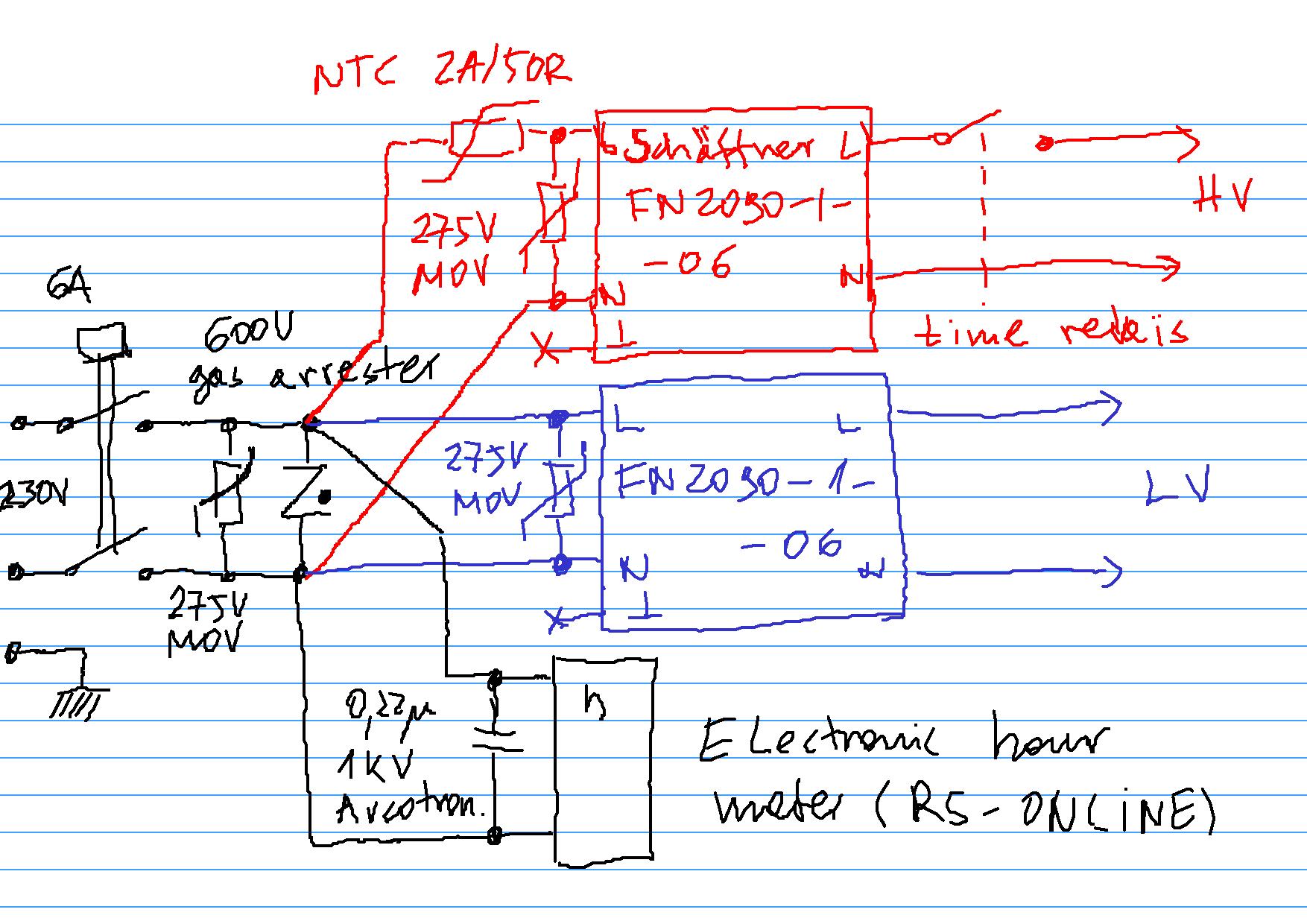
The power entry of the PSU box:
The PSU box continued:
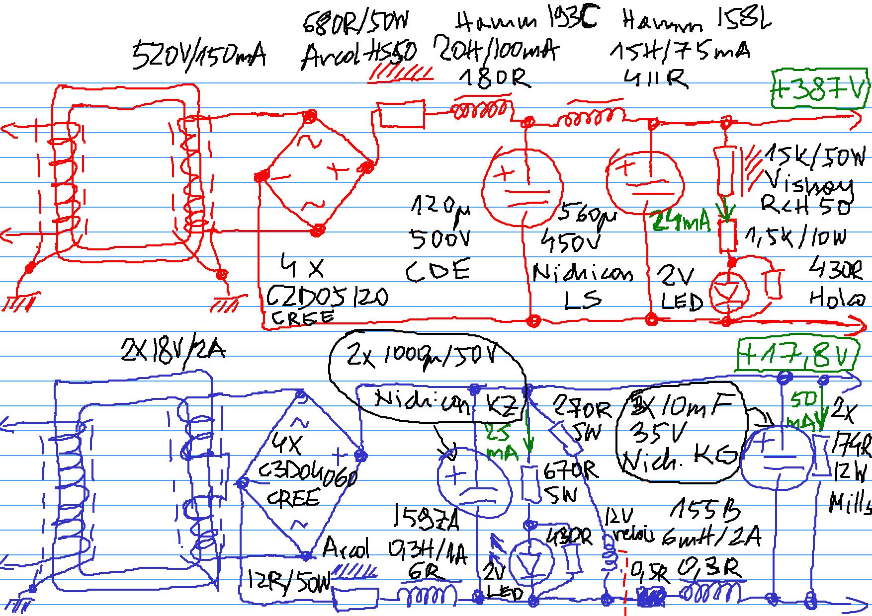
The power transformers where wound to my specs but still there was an element of surprise,
as I think I've specified the voltages at full load (or my winders got it this way),
simultaneously oversizing the trannies few times...a stupid practice of me.
The trannies are C-core, isolation type (primaries and secondaries on different legs, double screened).
The input chokes are function of what my power transformers happened to be.
Since the HV one gives 520V,
I needed a 600V choke and hence a 193C-type. I've used somewhat higher cap values than Romy with
120uF and 560uF. Simulations did no show any significant increase in the current drwa w.r.t. the original
Romy's values. The 120uF cap is 500V and this is agoin the function of the tranny.
With LV I've made a stupid error thinking I could parallel connect
the heaters within 12AX7's and then CCS them...me idiot...good that I'd specigied the tranny for a FW rectifier
so doubling the votage to get 12.6V at the heaters was not a problem. The LV
input choke is a function of that, the 450mA heater current, and the Hammond range. The damping resistors
lower the Q to avoid resonant behaviour.
As you can see in the pics the power resistors are bolted to the 3mm alu mounting plate,
which is then connected via 10mm thick alu bridge to the radiator at the back (and the case). This keeps the temperature
inside the box down, even with the insane summer we have here in Barcelona now.
Will post the signal box schematics soon.
Romy: Thank you for the SUT teachings!
Rerurn to Romy the Cat's Site