| Search | Login/Register
   Home » Horn-Loaded Speakers» Macondo Frame modification. (47 posts, 3 pages)
  Print Thread | 1st Post |  
Page 1 of 3 (47 items) Select Pages:  1 2 3 »
   Target    Threads for related reading   Most recent post in related threads   Forum  Replies   Views   Started 
  »  New  The “Dead Points of Live Sound”..  Confused...  Playback Listening  Forum     28  326277  05-14-2005
  »  New  Macondo Horns: biography...  Macondo with Pussy Eyes....  Horn-Loaded Speakers Forum     2  62979  05-18-2005
  »  New  Macondo Alternation. Extending the LF line-array..  Macondo and not only Macondo positioning...  Horn-Loaded Speakers Forum     8  151026  10-29-2005
  »  New  Summary: my/your audio: year by year..  Happy 2024!...  Audio Discussions  Forum     45  393047  12-29-2006
  »  New  RAAL “Water Drop” tweeter for Macondo...  Your comment takes me by surprise...  Horn-Loaded Speakers Forum     77  924647  02-16-2007
  »  New  Macondo's Axioms: Horn-loaded acoustic systems..  A link to another thread....  Horn-Loaded Speakers Forum     120  680280  07-29-2007
  »  New  My (Amplification + Acoustic System): what is next?..  Macondo and Melquiades in the NEW room....  Audio Discussions  Forum     41  314776  01-10-2008
  »  New  Macondo’s MiniMe or about Pilot Acoustic Systems..  Injection Pilot?...  Audio Discussions  Forum     213  1980391  09-03-2008
  »  New  MacondoLite..  The Count Alessandro di Cagliostro’s methods....  Horn-Loaded Speakers Forum     18  185864  08-15-2009
  »  New  Adding one more non-spherical to Macondo...  Horn suggestions for 300Hz-1000Hz channel...  Horn-Loaded Speakers Forum     23  249202  12-15-2010
  »  New  Stands for Super Melquiades...  Wavac Audio Lab 805MK-II...  Melquiades Amplifier  Forum     6  76154  08-02-2006
  »  New  Rakeshorns..  Excellent walls....  Horn-Loaded Speakers Forum     33  299051  08-26-2011
  »  New  Looking to brainstorm stand ideas..  Fair enough...  Horn-Loaded Speakers Forum     2  19842  12-06-2011
  »  New  Canadian Speaker Proposal..  Drivers/Speakers As Filters...  Horn-Loaded Speakers Forum     56  357382  06-21-2013
  »  New  Deep End DIY - Australian take one Macondo...  It is simple, but......  Horn-Loaded Speakers Forum     87  319066  01-20-2016
12-22-2006 Post mapped to one branch of Knowledge Tree
Romy the Cat


Boston, MA
Posts 10,156
Joined on 05-28-2004

Post #: 1
Post ID: 3339
Reply to: 3339
Macondo Frame modification.

Since my new tweeter will be arriving in a month or so I am slowing completing the ideas of finalizing the frame of my Macondo. Whoever dealt with 4-ways horn-lodes know that framing of this thing is quite tough. It should be functional and none-abusive at the same time and it is quite hard to accomplish. Also, horns do feel the presence of frames and fewer frames is always better. A horn just handing in open air – is absolutely the best.

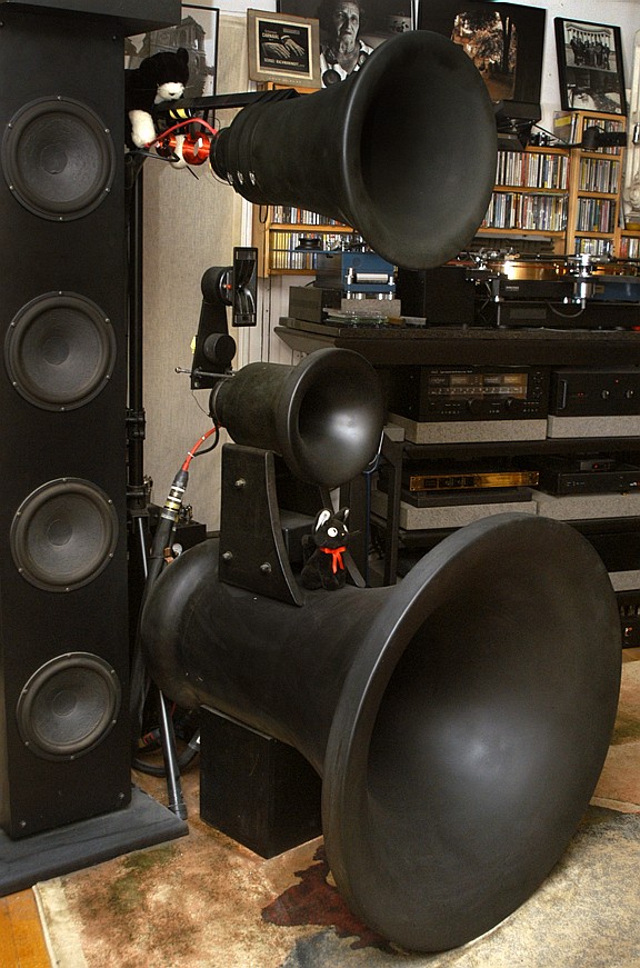
I really satisfied and very comfortable with the way how in Macondo upperbass horn and MF horn mounted. The upperbass horn sites in the custom profiled wood assemble, filed with sand. It is very firm, very heavy and it does perfect foundation for Macondo.
SecondTrans.jpg

There is a custom fame made for MF. I spent quote a time to design and to make it. I find it quite elegant looking and very functional as it does allow the reflections to bypass itself and do not bounce them back. The MF horn is hard-coupled to the MF frame but the MF frame is decoupled form the upperbass horn and sits in the upperbass horn under own weight. To insult the injury I have 40 point lead blob sitting inside the MF frame. A tweeter will be sitting above and behind the MF horn, on own mounting harness. I do not have it yet but everything will be quite straight forward there…

So, the entire assembly is feely might be moved in it’s search of the  DPoLS (there are carpet sliders under the bass horn frame). However, the lower MF horn (LMF) screws the entire picture.

When I added the lower-mid-frequency channel - LMFC (or as I called it “the fundamentals channel”) I really did not want to put any frame in front of the MF of HF channels and I ended up mounting the LMFC from behind. It works very well sonically, but it makes the entire Macondo very-very difficult to move as now I need to move the Macondo assembly and then, separately, to move the tripod with LMFC, along with all that complex system of contra-weights and LMFC alignment.
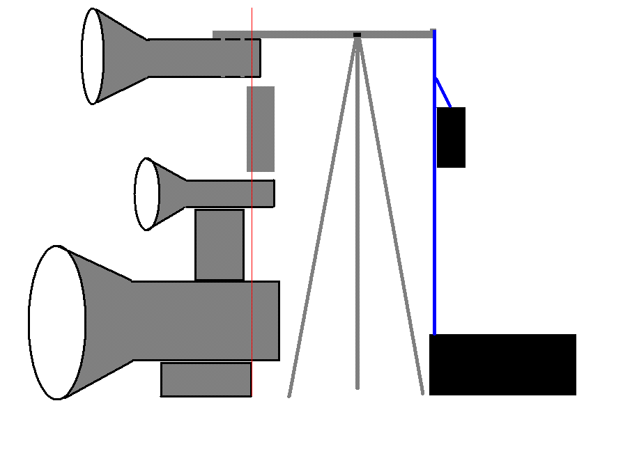
MacondoFrame1.gif

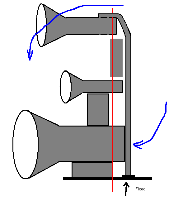
So, my idea is to make the entire 4-ways Macondo to be uni-moble and still to keep all Macondo’s accomplishments not compromised. What I am thinking is to put under the bass frame a plate with harnesses to hold the bass frame. On the back side of the bottom plate I would have a shoe in witch I vertical profiled rod will go. This vertical bar will run all the way up and will be lying in the back of the upperbass horn.
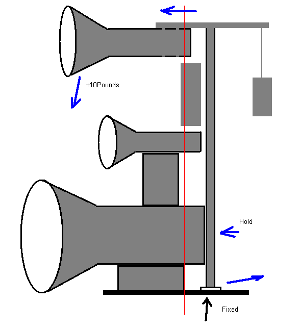
MacondoFrame2.gif

MacondoFrame3.GIF

It is very simaple to visualize everything form picture. I like the idea and the only concern I have is that the vertical rod (and partially if it will loaded is as it is on the last image) might bend or curve. Perhaps by selection of a correct profile for the rod or the rod’s material, I would be able to prevent curving but… still it will be ~7” tall – and will be caring quite a mass…. Perhaps I would come up with gaskets between the back of upperbass horn and that vertical rod that would allow to offset the rod’s bending and to keep the axe of LMFC channel parallel to the MF? However if the rod bends then most likely the depth of the banding will be changing with time… I need some consulting with metallurgists….

Rgs,
Romy the caT


"I wish I could score everything for horns." - Richard Wagner. "Our writing equipment takes part in the forming of our thoughts." - Friedrich Nietzsche
12-22-2006 Post does not mapped to Knowledge Tree
Romy the Cat


Boston, MA
Posts 10,156
Joined on 05-28-2004

Post #: 2
Post ID: 3344
Reply to: 3339
The mobile tripod for Mocondo.
Ok, it looks I have conceptualized how my “mobile tripod” for Mocondo will look like. Now I need to find some kind of home welding machine of gas metal cutter to put this thing together as my machinist will defiantly refuse to make it...

The caT


"I wish I could score everything for horns." - Richard Wagner. "Our writing equipment takes part in the forming of our thoughts." - Friedrich Nietzsche
12-23-2006 Post does not mapped to Knowledge Tree
jessie.dazzle


Paris, France
Posts 456
Joined on 04-23-2006

Post #: 3
Post ID: 3349
Reply to: 3339
Macondos Frame Mod Variant
Romy,

Here are some images of a slight variant of your Macondo Frame proposal.


This version has the Fundamentals horn more rigidly coupled (this may or may not be desirable) and does not require a counter weight. It may also be a little more compact, allowing you to place it nearer to your Lower Bass Channel towers.

To symplify construction, the "zig-zag" triangulation could be replaced with a sheet or a plate, acting as a shear panel.

Since your Mid Bass and MF horns are adjustable for time alignment, it may be worth mounting the Fundamentals horn on a sliding mechanism so that you can easily adjust it like your other channels. The HF channel could be fixed (non adjustable) and used as the reference for adjustment of all other channels.

Regards,

jd*


How to short-circuit evolution: Enshrine mediocrity.
12-23-2006 Post does not mapped to Knowledge Tree
Romy the Cat


Boston, MA
Posts 10,156
Joined on 05-28-2004

Post #: 4
Post ID: 3351
Reply to: 3349
Macondo Version 3.2

Thanks Mark,

I was rethinking it and I come up with something along with what I depicted below. The main vertical rod become a triangular monopod and it will maintain vertical position because it will have a second point of contact” it will lay ay the back of the upperbass horn. I think this solution is more interesting and very much accomplishable.


The caT


"I wish I could score everything for horns." - Richard Wagner. "Our writing equipment takes part in the forming of our thoughts." - Friedrich Nietzsche
12-23-2006 Post does not mapped to Knowledge Tree
Paul S
San Diego, California, USA
Posts 2,656
Joined on 10-12-2006

Post #: 5
Post ID: 3354
Reply to: 3351
Now you're talking
As simple as does the job.

Using the right size section and the right gauge, along with good welds, you could simply use square section tubing on a heavy plate, like you pictured a couple of iterations above.  This would reduce bulk and complexity and keep cost down as well, because you would use all commonly stocked components and minimal fabrication.  Steel (or aluminum) itself is cheaper than welds.  I am not tech enough to offer drawings but I have been a builder for 40 years, and I have enough experience to know that even your most streamlined example could be made to work, if that's what you wish.  Any competent professional welder/fabricator could figure this out and do it for you.  You would likely have to design in some slop/adjustment and provide oversight, but I have complete knotheads making more complicated things for me all the time.

But clearly, you have been through this sort of thing before.

Best regards,
Paul S
12-24-2006 Post does not mapped to Knowledge Tree
Romy the Cat


Boston, MA
Posts 10,156
Joined on 05-28-2004

Post #: 6
Post ID: 3355
Reply to: 3354
Macondo Version 3.4
Actually it was not my last design. The very last, the one that I love is below. It has elegance of a sea sail and has some sculptural dynamics. I do like it a lot and the design also take care about all levers and the centers of the masses….


The caT


"I wish I could score everything for horns." - Richard Wagner. "Our writing equipment takes part in the forming of our thoughts." - Friedrich Nietzsche
12-24-2006 Post does not mapped to Knowledge Tree
Paul S
San Diego, California, USA
Posts 2,656
Joined on 10-12-2006

Post #: 7
Post ID: 3356
Reply to: 3355
Very nice, for just the reasons you mention
And considerably more expensive because it's made from custom-cut heavy plate stock (with more waste) rather than generic extruded stock (with little or no waste).

But that never stopped you before...

Best regards,
Paul S
12-24-2006 Post does not mapped to Knowledge Tree
jessie.dazzle


Paris, France
Posts 456
Joined on 04-23-2006

Post #: 8
Post ID: 3357
Reply to: 3356
Getting that Curve
Paul is correct ; you could make the vertical member from one thick hollow pole or tube and be done... this is by far the most economical route.

But since we like that curve in your latest design... (this could become a very powerful sculpture) :

Economical solution : Use several 3" square section hollow tubes standing vertically, lined up behind the rear chamber of your Bass horn... The tubes could then be welded to eachother (a small 1" weld every foot). The whole stack of tubes could then be cut to the curve you desire (like a pipe organ or a pan flute).

To cut along the curve you would probably want to find a shop with a large band saw (and a guy who is not in a hurry), as a torch, plasma, or laser cutter would make a mass of it.

The resulting vertical member would be dead stiff.

More expensive, more involved, but more professional solution : Make a hollow core member from laser cut sheet (4mm thick).

Places that do laser cutting can read .dxf .cdr .ai .tcw and .dwg files. This means that you don't need to use a CAD program, a simple vector drawing program such as CorelDRAW or Adobe Illustrato will export the info in the required file format.

Final assembly should be quite easy for a good welder, as the visible welds would all be on out-facing corners.

You could use the same technique to make the horizontal member (which would benefit from a greater vertical section where it meets the main member).

Potential work of art : Ultimately, it would be best to hand the project to someone like this guy here :
http://www.emetalsculpture.com/thesculpture.html

If you go with laser cutting, you can put curves wherever you desire... You could for example make the base of the vertical member not only deeper, but also wider...

If you go this far you will probably want set the finished work of art where you can really stand back and see it... which probably means moving to a place large enough for that pair of 40Hz horns !

Regards,

jd*


How to short-circuit evolution: Enshrine mediocrity.
12-24-2006 Post does not mapped to Knowledge Tree
Romy the Cat


Boston, MA
Posts 10,156
Joined on 05-28-2004

Post #: 9
Post ID: 3358
Reply to: 3357
Macondo Version 3.6

I made some further adjustments, added details to the tweeter and so on. It looks good. Yes, to make this sail will be complicated and price. Not to mention that the thing will be over 6 feet long. I will not start doing it until I have the tweeter in my hands. I need to consult my machinist and see what he will suggest.  As I feel it all will boil down to the selection of metal. If it were steel then it will be thin, perhaps 3/8”, heavy like hell and welded. If it were aluminum then it might be 2-3”, bolted from top and bottom and disassembleable. The good part about aluminum that I could use a 4” sheet and CNC it to make 4” at the bottom and I would say 2” at it’s top. I might be very cool looking. The only thing that I do not know if aluminum-make threads in the bold will be able to handle the pressure of that lever atop. Well, we will see what the specialists say. There are other options – there is architectural plasmas – they are very strong, CNCable and could go the job but they are way more expensive. An aluminum leftover sheet of 4” that I need will cost in my local metal supply shop around $300-$400, though the architectural plasmas of the necessary strength will cost over a thousand dollars…. Anyhow, will see. The more people I talk about it the more I learn and the more options become available….


The caT


"I wish I could score everything for horns." - Richard Wagner. "Our writing equipment takes part in the forming of our thoughts." - Friedrich Nietzsche
12-24-2006 Post does not mapped to Knowledge Tree
Romy the Cat


Boston, MA
Posts 10,156
Joined on 05-28-2004

Post #: 10
Post ID: 3360
Reply to: 3358
Macondo Version 3.7

I did some further thinking. I slightly modified the sketch, more or less reflecting the actually dimensions of the elements. The tweeter was too large and the upper horn was too small.  The current downing is more reflects the current Macondo fell.

I was trying to keep the depth smaller as the upperbass horn is too long anyhow. I think if I go for 8” vertical steel plate of 3/8 or ½ of inch then it will be manageable enough and not horribly heavy. The only thing is that I would like to have the frame dissembleable and detachable from the bottom plate (still to be very firm). So, if I weld-in 4 large cylinders at the bottom of the vertical panel, with steel threads and then tight them with bolds for the bottom then it should do. In fact all of this because not really complicated to render….

The caT


"I wish I could score everything for horns." - Richard Wagner. "Our writing equipment takes part in the forming of our thoughts." - Friedrich Nietzsche
12-25-2006 Post does not mapped to Knowledge Tree
jessie.dazzle


Paris, France
Posts 456
Joined on 04-23-2006

Post #: 11
Post ID: 3361
Reply to: 3360
Some further thoughts
Yeah, the scale of things looks more like what I would expect... In my images I used the models of horns I am building for myself... so the Fundamantals horn is not the same as yours... also, it is placed too close to the listener, but was just trying to get a stand mocked up.

Regarding your latest version : Yes your plate will have to be quite thick if it is not going to sway or twist... you can of course do it, but you will need to start with a very flat plate (not always the case with plate), and may want to consider securing it with a larger diameter and longer (higher) cylinders, cross bolting them through the plate.

My intuition : Considering a 1/2 inch plate, the 8 vertical feet, and the load (with which I have become very familiar)... I feel you would be better off with a section offering more inhernet natural resistance both lateraly and torsionaly. Extending the cylinders a lot further up the plate would be one way to achieve some of this.

Here's another idea : You could use the plate as in your latest images, but sandwitch it between two smaller, thinner plates of similar shape, spaced out an inch or two from the central plate. These side plates would not go up as high (maybe only 6 feet). They could be bolted to the main plate using long bolts and cylindrical spacers that hold them out from the central plate. Large diameter spacers and properly torqued bolts would give you plenty of additional resistance in bending and torsion, while offering a more secure mounting point at the base. You would preserve the nature of your design, and the whole thing could be unbloted.

A nice progressive increase in resistance could be acheived via use of longer spacers near the base, and shorter spacers toward the top, giving you a curve when veiwed from the front (once the side plates have been sucked in by the tension of the bolts). You'd of course have to first suck in the side plates with big clams before marking the bolt holes.

I can help if you'd like to see any of your ideas in more finished computer renderings.

Regards,

jd*


How to short-circuit evolution: Enshrine mediocrity.
12-25-2006 Post does not mapped to Knowledge Tree
Romy the Cat


Boston, MA
Posts 10,156
Joined on 05-28-2004

Post #: 12
Post ID: 3363
Reply to: 3361
Macondo Frame, Version 4.0

Well, this for the tip of multi-layering the vertical panel. I like it a lot. I will allow keeping the mild panel thinner and more “airy” visually. The total high of the thing will be not 8’ for rather somewhere slightly above 6’. Also, I review the way in which the tweeter might be mounted. Since it is HF transducer and since it will be made in the shape  “drop of water” (to minimize the off baffle reflections) I think the pedestal via which I was thinning to couple the tweeter o MF horn (pictures above) will not be an optimum solution. I less care about the reflection as the tweeter is line array and will have quite narrow verticals radiation but still, I do not like any baffle-like impediments near tweeters.


The caT


"I wish I could score everything for horns." - Richard Wagner. "Our writing equipment takes part in the forming of our thoughts." - Friedrich Nietzsche
12-25-2006 Post does not mapped to Knowledge Tree
Paul S
San Diego, California, USA
Posts 2,656
Joined on 10-12-2006

Post #: 13
Post ID: 3366
Reply to: 3363
"T" for two
On the cheap:
A few renditions ago you showed a "T" section for the main vertical menber, and this would allow you to use thinner stock without the lateral or torsional issues the nominally-two-dimensional "sail" would otherwise engender.  No reason why the reinforcing part couldn't taper as it went up, also, which would blend better with your main "sail".

A la Brancuzzi:
Or, you could use thinner plate in a "sail-shaped" version of the triangular-section vertical you've also shown, by using a longer, wider "section" at the base, then taper down both length and width as you ascend.  More welding, but plate could be pretty thin, and it would be LOTS less expensive than any milled versions you've mentioned.  Then just weld a thick plate inside the base to tap for threads and through-bolt with tapered flat-head Allen bolts from the underside of a thick base plate.  For that last psycho touch, fill it with sand.

Le voila'.

Paul S
12-26-2006 Post does not mapped to Knowledge Tree
Romy the Cat


Boston, MA
Posts 10,156
Joined on 05-28-2004

Post #: 14
Post ID: 3373
Reply to: 3366
I'm good for now....

Yes, Paul you are right. In my chaise for “cosmetics” the economic aspect jumped out of my aim. The last design would require 6 panes for a par of the loudspeakers it is might be pricey. McMaster quotes a steel panel of 3/8” by 6” by 8” somewhere near $450. I can do twice-trice less expansive in a local Admiral Metal suppler, not to mention saving a lot on shipping of the things. Still, if you add labor and finish than it might be in realm of a couple thousands dollars at its best…. It would be possible to simplify the things as at the image below; it would require juts one panel per speaker. Still, I heed to expose all it to the objection machinist and see where it might go from there. Hey, where the Cogent’s Rich and Ottari’s Paul are when I need them, their input would be very valuable. Anyhow, I think I have enough ideas to wait until the tweeter would be done and then finalize the design. For now, I’m good with what I and you guys have came up and it is a good staring point to lay down the objective to the attention of the professionals. Later on I will make the drawing in the exact dimensions and my machinist will asses how much thinkers and support that vertical frame need to hang that “fundamental channel”

The caT


"I wish I could score everything for horns." - Richard Wagner. "Our writing equipment takes part in the forming of our thoughts." - Friedrich Nietzsche
12-26-2006 Post does not mapped to Knowledge Tree
jessie.dazzle


Paris, France
Posts 456
Joined on 04-23-2006

Post #: 15
Post ID: 3375
Reply to: 3373
Stacked Tube Version

At the risk of overloading you... Here are a couple of quick computer drawings showing a version made from 2 inch steel tube... Material cost would be very low.

jd*

Tube Frame 01b.jpgTube Frame 04b.jpg


How to short-circuit evolution: Enshrine mediocrity.
12-26-2006 Post does not mapped to Knowledge Tree
Romy the Cat


Boston, MA
Posts 10,156
Joined on 05-28-2004

Post #: 16
Post ID: 3376
Reply to: 3375
An echo of Hindenburg on my listening room.

Wow! Thank you! What a brilliant idea to make the vertical poll not solid but to assemble it with triangular pipes of the different length! I love how it looks. (I think it was proposed before but I did not visualized it without image)

The only concern I have that the rectangular tubing available with .065" wall-thickness maximum and it might make the strength of the vertical panel not as effective. For instance on the drawing that you made the force of the upper horn sits juts upon 2 tubes and the shorter tubes do make as much support as it would be in case of solid plate. Sure, if it would be possible to hard -tight the tubes, like welded… but I still do not know how strong it would be. Surely I need some machinist to assess all of it….

Another idea would be to hand the upper-horn in its position with a miniature hydrogen-filed dirigible, flying next to the room ceiling ... :-)


"I wish I could score everything for horns." - Richard Wagner. "Our writing equipment takes part in the forming of our thoughts." - Friedrich Nietzsche
12-26-2006 Post does not mapped to Knowledge Tree
jessie.dazzle


Paris, France
Posts 456
Joined on 04-23-2006

Post #: 17
Post ID: 3378
Reply to: 3376
Tube Frame : Some Thoughts on Construction
You are correct, the idea is to "hard tie" the tubes together (otherwise you don't get the rigidity... think of a paintbrush where the paint has dried in the bristles... this is what you want). You would need small welds between each tube... a 1 inch weld every foot would be plenty (on both sides)... avoid running long welds which would cause the whole thing to over heat and probably twist. First choice here is to use a TIG torch... Next would be MIG... both keep the heat down, but TIG ususally ends up prettier.

In the drawings, all tubes are of 2 inch square section (not rectangular... those cost more)... cutting them at an angle makes them look like they have a rectangular section.

For the horizontal upper member, you could of course use three tubes (instead of two) this would definitely give you enough beam strength.

.065 wall thickness is enough if done right. The important thing to remember in this case is to attach the members in such a way that you load the joints in shear (clamping the vertical member between the two base parts for example) and distribute the load over a large area.

If you want to get fancy, one elegant means of attaching the upper member would be to not attach it at all, but to put a notch in its under side and set it on a pivot ; give it a short tial which would hang out past the rear, then string a cable from the tail, down vertically to an attachment point low down on your vertical member. Use an in line cable tensioner to adjust the angle of the horizantal support.

Back to work...

jd*


How to short-circuit evolution: Enshrine mediocrity.
12-27-2006 Post does not mapped to Knowledge Tree
hagtech


Hawaii
Posts 117
Joined on 02-13-2006

Post #: 18
Post ID: 3385
Reply to: 3378
Hanging Ten
Romy, I don't know what it is, but something bothers me about the way the upper horn hangs.  All other drivers are supported from bottom, that one from the top.  This is just gut, but it doesn't seem right to me.  I get this sick feeling of wobble and resonance.  Perhaps merely irrational thoughts.

Is there any way possible to offer a support from the bottom?  That is, without disturbing the gas field in front of the tweeter.  I don't think it is as much an issue of top or bottom as it is that large moment of inertia I see with the tall stand.

jh
12-27-2006 Post does not mapped to Knowledge Tree
Romy the Cat


Boston, MA
Posts 10,156
Joined on 05-28-2004

Post #: 19
Post ID: 3387
Reply to: 3385
Horn is not Saddam – I feel it could be hanged.

 hagtech wrote:
Romy, I don't know what it is, but something bothers me about the way the upper horn hangs.  All other drivers are supported from bottom, that one from the top.  This is just gut, but it doesn't seem right to me.  I get this sick feeling of wobble and resonance.  Perhaps merely irrational thoughts.

Is there any way possible to offer a support from the bottom?  That is, without disturbing the gas field in front of the tweeter.  I don't think it is as much an issue of top or bottom as it is that large moment of inertia I see with the tall stand.

Well, it is rational thought, I did think about it. Let look at the subject deeper.

Are any ways to support the upper-horn from bottom?  There are 3 ways that contemplated in past. It was use of thin tripod-like tubing coming from the upper-horn all the way to the bottom (similar to what Avantgarde did). This would put the speaker inside a virtual pyramid. I do not like how it looks like, not to mention the presents of one and a half rods ahead of the tweeter. Another option that I contemplated was use of two sides, similar to what Cessaro GAMMA does. I decided do not do it as I would like to keep HF and MF horns as free-hanging as possible because I feel that proximity of any boundaries near horn mouth screw imaging. The third way that I was thinking was to make the tweeter and the upper-horn frame integrated.  It would require an enormously strong enclosure for tweeter and very-well designed tweeter-frame. I am not settled with tweeter, an nowadays a new custom tweeter is being built for me. Theoretically after I get the tweeter and if it will perform up to the demands then it would be possible to contemplate the tweeter-frame integrated design. Still, whatever it might be it should connect the tweeter from it’s back only… it is EXACTLY what I a doing now anyhow… so, I disregarded the idea of making Macondo as “a pyramid of the horns” and decided to hang my upper-horn.

Let look what we have as “the problems”. The upper-horn is 600-1000Hz, and it is a compression drivers…. means relatively high frequency, very low exertion, low mass, low inertia. The upper-horn I made think (as you can see at the picture in the beginning of the thread). It is approximately 30 pounds + ~12 pounds of the driver. Now, correct me if I’m wrong but as far as I understand it - any theoretical resonance-induced by swinging would act against the center of mass. The center of mass is far ways on the horizontal level that makes the total applied mass of the horn assembly way over 200 pounds. In the past, contemplating all of it I made soft suspension of the upper-horn in its horizontal arm. It was immense complex setting where the horn was handing on 2 rubber suspenders. Interestingly that the decupling produce ABSOLUTELY NO DIFFERENCES to the actual SOUND OF THE HORN and I decided to go for hard-coupling between the horn and the arm. I also trued adding the additional 150 pounds atop of the horn (5 bags of the led shots) and it HAD NO SONIC EFFECT…

So, what I concluded was that any resonances that might take place in the “handed horn” are imaginable or negligible.  At least so far I was not able to hear the problems attributed to the swinging resonance…. So, I do not care about it anymore, and unless I head something that I find is “not right” I will not dig deeper. Generally purring a statescope on the horn says a lot what is doing on… The “hanged horn” responses via statescope identically to the same horn sitting on carpet. So, as they say out of sight – out of mind….

Rgs,
Romy the Cat


"I wish I could score everything for horns." - Richard Wagner. "Our writing equipment takes part in the forming of our thoughts." - Friedrich Nietzsche
03-26-2007 Post does not mapped to Knowledge Tree
Romy the Cat


Boston, MA
Posts 10,156
Joined on 05-28-2004

Post #: 20
Post ID: 4073
Reply to: 3339
It is comming.....
OK, I’ve been for a while but I think I am ready to move forward. Sine the project with Water Drop Tweeter is over successfully and I know the final detentions of the tweeter and its radiation parent that will be used in Macondo I might finales everything with the Macondo new frame. I will be great to get rid the chains, contra-weights and tripods eventually….

After further consecration I made my mind to go for a single narrow vertical poll perusing the smallest footprint possible. The drawing it made and sent to my mashie shop today. The way in which it is designed the horns of Macondo will be easy movable to its search of the new DPoLS location ...

I am exited…
The Cat


"I wish I could score everything for horns." - Richard Wagner. "Our writing equipment takes part in the forming of our thoughts." - Friedrich Nietzsche
Page 1 of 3 (47 items) Select Pages:  1 2 3 »
   Target    Threads for related reading   Most recent post in related threads   Forum  Replies   Views   Started 
  »  New  The “Dead Points of Live Sound”..  Confused...  Playback Listening  Forum     28  326277  05-14-2005
  »  New  Macondo Horns: biography...  Macondo with Pussy Eyes....  Horn-Loaded Speakers Forum     2  62979  05-18-2005
  »  New  Macondo Alternation. Extending the LF line-array..  Macondo and not only Macondo positioning...  Horn-Loaded Speakers Forum     8  151026  10-29-2005
  »  New  Summary: my/your audio: year by year..  Happy 2024!...  Audio Discussions  Forum     45  393047  12-29-2006
  »  New  RAAL “Water Drop” tweeter for Macondo...  Your comment takes me by surprise...  Horn-Loaded Speakers Forum     77  924647  02-16-2007
  »  New  Macondo's Axioms: Horn-loaded acoustic systems..  A link to another thread....  Horn-Loaded Speakers Forum     120  680280  07-29-2007
  »  New  My (Amplification + Acoustic System): what is next?..  Macondo and Melquiades in the NEW room....  Audio Discussions  Forum     41  314776  01-10-2008
  »  New  Macondo’s MiniMe or about Pilot Acoustic Systems..  Injection Pilot?...  Audio Discussions  Forum     213  1980391  09-03-2008
  »  New  MacondoLite..  The Count Alessandro di Cagliostro’s methods....  Horn-Loaded Speakers Forum     18  185864  08-15-2009
  »  New  Adding one more non-spherical to Macondo...  Horn suggestions for 300Hz-1000Hz channel...  Horn-Loaded Speakers Forum     23  249202  12-15-2010
  »  New  Stands for Super Melquiades...  Wavac Audio Lab 805MK-II...  Melquiades Amplifier  Forum     6  76154  08-02-2006
  »  New  Rakeshorns..  Excellent walls....  Horn-Loaded Speakers Forum     33  299051  08-26-2011
  »  New  Looking to brainstorm stand ideas..  Fair enough...  Horn-Loaded Speakers Forum     2  19842  12-06-2011
  »  New  Canadian Speaker Proposal..  Drivers/Speakers As Filters...  Horn-Loaded Speakers Forum     56  357382  06-21-2013
  »  New  Deep End DIY - Australian take one Macondo...  It is simple, but......  Horn-Loaded Speakers Forum     87  319066  01-20-2016
Home Page  |  Last 24Hours  | Search  |  SiteMap  | Questions or Problems | Copyright Note
The content of all messages within the Forums Copyright © by authors of the posts