| Search | Login/Register
   Home » Melquiades Amplifier » Planning my DSET (187 posts, 10 pages)
  Print Thread | 1st Post |  
Page 9 of 10 (187 items) Select Pages:  « First ... « 6 7 8 9 10 »
02-03-2019 Post does not mapped to Knowledge Tree
Romy the Cat


Boston, MA
Posts 10,049
Joined on 05-28-2004

Post #: 161
Post ID: 25278
Reply to: 25274
It is all good.
 anthony wrote:
First was the issue with the 6e6p  for the HF Channel not being able to draw enough current.  I checked the bias and it was fine and the potentiometer allowed plenty of adjustment so I changed nothing in the circuit.  A new tube was swapped in and bingo! the current is back and all is good. 

Hm, I did not understand that you did not start with it. It is always one tube has less current them others. In my estimation 1 our 10 tubes of this class are not useable. The irony that some (!) of them still sound fine despite lower current. The 6e5p has higher ration of not usable tubes, I would say 1 our 7 tubes. They are not defective tubes, it is just the bias setting not wide enough to cover them. You might put a bias attenuator in play, I did experiment with it and in my final design I did not do it intestinally. I discover that in most of the cases the low current tubes with lower current do sound worse. I think it has to do with cathode potency and then we drop bias too much to help the tubes. To evaluate each tube and to see if it sounds good at lower current is too much pain and it much easier to get a new tube. I paid for my 6e6p under $3 per tube, so why bother…
 anthony wrote:
All that I can think is that all the time that I ran that tube without pin 8 grounded has worn it out and it may be near failure.  When I first left the amp on for several hours a couple of weeks ago now the current from that rube was fine and it slowly dropped over time.  However, the three 6c33c channels were varying as well so I did not think too much of it.  The new tube pulls the required current with the pot somewhere near the middle of its range and I will leave the amp going all day today with the hope that the current will not fall as it did with the previous tube.

Be prepared to trash all tubes that you use during the design stage. I did some very barbarian this to them during my expedients and during my act of building stupidity. So, as you have all your operation points locked  and the amp function properly then juts put the set of the “design phase” tubes in a separate box and use all new tubes.

 anthony wrote:
My second problem was not being able to set the DC Offset to zero.  It sat at about a minimum of 230mV plus or minus 15mV regardless of the gas tubes I randomly swapped in there.  I tried half a dozen all up and decided that the issue was elsewhere.  What I did in the end was replace a 1k resistor that leads into the 100k potentiometer for trimming DC on the positive side with a 100k resistor, so 100 times larger.  The offset now trims to zero with the pot close to halfway through its travel.  Romy, I don't know if that is an error on the schematic or if I have some other issue, but the offset seems stable. 

 Nope, there is no error on the schematic, you are just the recipient of a very good design. :-) I’m not kidding, let me to explain. You can put in there 10M resistor and get rid of 420K resistor and will be able to adjust anything. The resolution of the agistment will be very low however. The 420K resistor acts as buffer that slightly decuples the rheostat from the signal. The 100K variable resistor has this value because a good feeling between the resistor turns of the voltage if balances. And the 1k resistor is a wild card joker that set all thing in place. The pression of the positive supplely is very had to estimate accurately. It balances 6 channels and the voltage of your positive supply transformer is not identical to mine. It should not be. The 1K resistor before the potentiometer is not necessary from voltage perspective but is necessary as independent adjustment tool. Your experience is a perfect illustration why the 1K resistor is there. As you can see I use the same 1K wild-card resistors earthenware.


"I wish I could score everything for horns." - Richard Wagner. "Our writing equipment takes part in the forming of our thoughts." - Friedrich Nietzsche
03-02-2019 Post does not mapped to Knowledge Tree
anthony
Posts 335
Joined on 08-18-2014

Post #: 162
Post ID: 25290
Reply to: 25278
Some time on it
Finally, it has happened.  Sound.  

Two weeks ago I had a couple of mates help me carry up and install the first DSET on its pedestal on the horn stack.  It was quite a bit of effort and three were definitely required for the heavy but delicate operations those last few inches into place.  Please forgive the sweaty hand-prints all over the black powdercoating, but here she is in place...

DSET on the stack.jpg

DSET on the stack 2.jpg


There was still a little soldering to do, speaker cables to attach, power cables to route, a few little last minute hiccups to solve.  I was so excited to just do it all then and there and light her up and listen that I did not trust myself not to overlook something, so I forced myself to wait.  Here and there over a couple of days I did the things necessary to fire her up until there came a moment when I had nothing left to do.

Below is how everything has been hooked up for the past twelve days...

DSET First Listening.jpg

Still no Upperbass horn and the Fane 8M sitting as shown on its box on a stool.  Channel C is another of those tiny silver speakers that you can see in front of the blue stool, but it is turned down as far as the attenuation goes.  So with zero tuning or tweaking or aligning or other general care and consideration that one would expect is necessary for decent sound, and of course without the full complement of channels and missing perhaps the most important horn, I recorded the very first sounds to come out of my semi-assembled Macondo by playing a song called Reckless, which is very well known in Australia and is sort of appropriate given the way that I have thrown myself into this project.

Romy, I get the idea that you are not favourable about videos of sound being posted, but for me this was a milestone moment, and it was not horrible.  I can post the video of the very first sounds if you would like to hear them, just let me know.

In the past 12 days I have listened every day and probably have 80 hours on the amplifier and speakers.  I tried going back to the excellent standmounts that I had been listening to previously, but even in comparison to the incomplete mono Melquiades/Macondo they just miss so much...I could not stay listening to them.  Now that the valve current draws have stabilised and have been set at the recommended positions things are even more dire for the standmounts.  Briefly, I tried altering some operating current on the valves and now have a better understanding of how DSET can be used to shape the sound.  It is one thing reading about it but another thing entirely when you turn a knob on the amp and a particular portion of the sound changes...such a powerful tool.

Still Macondo is incomplete and there are sound issues around the bass and upperbass, but mids and highs are delightful.  I have performed some initial measurements towards room treatment for bass and the left Bass Cannon in its current position is flat to 18Hz in room, which is excellent, but I do have some work to do to get flatter in-room frequency response below about 150Hz, with some room modes from about 40Hz.  Some impromptu trapping made a good start towards this goal, so hopefully over coming months I will eventually have a suitable solution.

So I must say thank-you Romy, for your assistance and willingness and support so far.  At this stage I really think that the whole effort will be worthwhile and that I should end up with an acoustic system to keep me satisfied for decades.  At least the first sounds are very, very encouraging...   
03-02-2019 Post does not mapped to Knowledge Tree
Paul S
San Diego, California, USA
Posts 2,570
Joined on 10-12-2006

Post #: 163
Post ID: 25291
Reply to: 25290
Here's to You!
Another major milestone in a very big project, and looking great, by the way!

Best regards,
Paul S

03-02-2019 Post does not mapped to Knowledge Tree
Romy the Cat


Boston, MA
Posts 10,049
Joined on 05-28-2004

Post #: 164
Post ID: 25292
Reply to: 25290
Very commendable and noble job
 anthony wrote:
Briefly, I tried altering some operating current on the valves and now have a better understanding of how DSET can be used to shape the sound.  It is one thing reading about it but another thing entirely when you turn a knob on the amp and a particular portion of the sound changes...such a powerful tool.
I am not sure I agree with it. I do not see in Milq a great ability to altering some operating points. The driver stage is set, you can drive 25% more or less current of voltage but I do not feel that it changes sound very drastically. The same is with output stage. It does change very slightly the damping of the output stage. Well, I need to admit that the ScanSpeak array are very sensitive to dumpling, I have written about it before. A normal speaker is not so sensitive to damping so much. What I disagree is that altering operation point is a way use DSET. If you say “charge of the OTP sections for each channel then I would say YES, this is how you charge the damping. Not the changing of operation points. The objective of operation point is to set the tube foe symmetrical clipping, nothing else\. It means that for a max power of operation against the very specific load the top at the bottom sinusoid much clip at the same time. The top is current and the bottom is voltage (or wise versa, I do not remember now), you need to make sure that when they clip it will be symmetrical. DSET should clip by transformer, not by driver tube. From all that was said it is understandable that there is not a lot of operation point flexibility in a well designed amp.
 anthony wrote:
Still Macondo is incomplete and there are sound issues around the bass and upperbass, but mids and highs are delightful.  I have performed some initial measurements towards room treatment for bass and the left Bass Cannon in its current position is flat to 18Hz in room, which is excellent, but I do have some work to do to get flatter in-room frequency response below about 150Hz, with some room modes from about 40Hz.  Some impromptu trapping made a good start towards this goal, so hopefully over coming months I will eventually have a suitable solution.

Flat to 18Hz is a bit too god to be true. Not that I do not feel that it will not go down to 18Hz, this is well expected, but to be flat from 100 to 18… I would not believe in such a luck. I do not say imposable as I have seen it. Do not waste you time on trapping and the reset of it. Finish you upperbass, connect the things and I will let you know what sweep you need to post to calibrate the things properly. Do not fight with you room. This is bridge to nowhere. You your room imperfection if you have them as you expressive tools and factor the imperfections into the Macnondo sound. As you done with upperbass I will teach you how to do it. Without the upperbass there is no need to listen the Macondo. With the rest you have doe a very commendable and noble job.

Rgs,
Romy the Cat


"I wish I could score everything for horns." - Richard Wagner. "Our writing equipment takes part in the forming of our thoughts." - Friedrich Nietzsche
03-02-2019 Post does not mapped to Knowledge Tree
anthony
Posts 335
Joined on 08-18-2014

Post #: 165
Post ID: 25293
Reply to: 25292
Not exactly flat to 18Hz...
There are still room modes to contend with the first starting at about 41Hz.

Here is an impedance plot of the left Bass Cannon as seen by the amplifier, so including speaker cable.

DATS First Cannon (Left).jpg


As you can see I managed to get Fs down to about 44Hz and it turns out and an impedance range of about 1.1R to 3.15R, which apart from the unavoidable resonance peak is pretty flat from 5Hz - 1kHz.  Due to their dimensions I've had to use a very particular damping scheme of the Cannons to get this 'flatness'.  I also made quite an effort to seal up my room to get best use of 'room gain'.

The left Bass Cannon measured at the listening position in my untreated room gives the following graph:
Trapdoor Down, windows all closed.jpg


So not exactly flat, but conforming quite closely to expected room behaviour.  I am confident that I can greatly flatten those hills and fill those hollows and have run a few tests with just a couple of bags of wall insulation brought into the room and have had improvements in all of the hollows of up to 15dB and the peaks have come down a few dB each.  41Hz, is the biggest challenge, but I think I will be able to knock a fair bit from it without too much treatment.

The Upperbass Horns are still a ways from finished, but I am certainly trying to get them finished.  In the meantime I will work on the second DSET and perhaps take some measurements and give this first one a thorough check-over now that it seems to be reliable.

Regards,

Anthony  
03-02-2019 Post does not mapped to Knowledge Tree
Romy the Cat


Boston, MA
Posts 10,049
Joined on 05-28-2004

Post #: 166
Post ID: 25294
Reply to: 25293
Your bass is better then you music, be carefull...
Well, it might sound as a heresy to you, but I personally consider the impedance curve is a bit irrelevant in this application. In this application you need to care only about only 2 things: if you have enough power in you LF DSET to drive your line array and the character of sound in LF. If I was you I would keep lowering damping, more and more idling the LF output stage until you will be in danger the amp approaching clipping. They relies the damping a bit if you feel that you get too SS type of bass or THEN play with plate current to fine tune the damping.
 
The frequency response is another matter. You need one channel, no time-window and the mike in the exact listening position. I presume that your amps the drive bass has no filters. Your upperbass in your room might be running down to 100-120Hz. The 42Hz is not a problem at all. The problem as I see it is in the 65Hz suck out, but do not worry there are many ways to deal with it.  What I would like to do is to give me the individual swipe the topmost driver in the LF array and the lowest. They must have a deferent repose and I would like to learn the difference.
 
We will need the sweep for the other channel and the summation of the R and L channels. What filter you built in into the Milq’s Chenal A? Are you drive the bass now from the Milq’s full range channel? If yes then the Milq’s full range channel and A channel have VERY deferent damping characteristics…
 
PS: Man, you need to play better music with your playback. I am serious, it is very discouraging to hear you play crap music. Please if you want me not to be demoralized then fake better music interest in your videos.


"I wish I could score everything for horns." - Richard Wagner. "Our writing equipment takes part in the forming of our thoughts." - Friedrich Nietzsche
03-03-2019 Post does not mapped to Knowledge Tree
anthony
Posts 335
Joined on 08-18-2014

Post #: 167
Post ID: 25295
Reply to: 25294
I deserved that
 Romy the Cat wrote:
Well, it might sound as a heresy to you, but I personally consider the impedance curve is a bit irrelevant in this application. In this application you need to care only about only 2 things: if you have enough power in you LF DSET to drive your line array and the character of sound in LF. If I was you I would keep lowering damping, more and more idling the LF output stage until you will be in danger the amp approaching clipping. They relies the damping a bit if you feel that you get too SS type of bass or THEN play with plate current to fine tune the damping.
 

No, not heresy at all.

The impedance plot is important from the perspective that the Cannons are an unusual shape and prone to ringing because of that shape, which shows up in the impedance plot as well as when listening to them.  The ringing is gone, and I managed that by observing the impedance plot and listening to them at the prototype stage.  Nowadays, in the absence of outdoor SPL measurements to check frequency response the impedance info is the best available indicator of frequency response and other abberations because I am not pulling down a stack and taking the whole system outside just to measure the free-air response of the speakers...there is no need for that.

I will play with damping the 6C33C when the system is a little more mature.
  
 Romy the Cat wrote:
  
The frequency response is another matter. You need one channel, no time-window and the mike in the exact listening position. I presume that your amps the drive bass has no filters. Your upperbass in your room might be running down to 100-120Hz. The 42Hz is not a problem at all. The problem as I see it is in the 65Hz suck out, but do not worry there are many ways to deal with it.  


That SPL curve and the one that I include below is the entire left side Bass Cannon driven by Channel A of my DSET, no other drivers are connected.  At 1r nominal impedance I cannot drive it with any other channel or even my SS amps.  A first order, 60Hz low pass filter is included.  Mic is at the exact listening position

In the graph below you will see two lines:  blue is the empty room; brown/yellow is with the addition of two bags of polyester wall insulation (still in the bag) sitting in the corner behind the Bass Cannon being driven.

SPL Greenstuf 2 bags.jpg

...the 65Hz hole is more or less gone.  I think that upperbass hole can be filled reasonably well just with a little more room treatment.  The 40-55Hz stuff a little less easy but hopefully it will come together without too much effort with room treatment.

 Romy the Cat wrote:
 What I would like to do is to give me the individual swipe the topmost driver in the LF array and the lowest. They must have a deferent repose and I would like to learn the difference. 
  
We will need the sweep for the other channel and the summation of the R and L channels. What filter you built in into the Milq’s Chenal A? Are you drive the bass now from the Milq’s full range channel? If yes then the Milq’s full range channel and A channel have VERY deferent damping characteristics… 


I can give you the response of the top and bottom driver of the Cannons.  It is a fair bit of messing around not to unwire and measure but to wire the things back up...I have not left enough room for my fingers to easily get to the bolt, and wiring it up the first time took half and hour.

The rest of that stuff will need me to finish the second DSET and hook it up.  That will be a couple of weeks.

 Romy the Cat wrote:

PS: Man, you need to play better music with your playback. I am serious, it is very discouraging to hear you play crap music. Please if you want me not to be demoralized then fake better music interest in your videos.


Yeah, sorry.  It is a song from my childhood that I really loved at the time [and still do].  I am late to classical music...my parents are both country kinds of people but Mum still listens to a lot of older pop and a bit of jazz.  Would you believe that my interest in classical was seeded by very late night driving in my 20's where I would leave where I was working and drive 4 hours home through the rough and winding and almost non-populated hills and get in around midnight?  I would purposefully leave at about 8pm because that was when the friday night concert started on ABC Classic FM and it was listening to symphonic music in particular that kept me awake...complete engagement for hours and the trip was gone in the blink of an eye.

It has only grown from there.  If you have any suggestions for music please let me know.  I was thinking some Heifetz/Max Bruch Violin Concerto 1 that I discovered from the same FM station in my late 30's. 


03-03-2019 Post does not mapped to Knowledge Tree
Romy the Cat


Boston, MA
Posts 10,049
Joined on 05-28-2004

Post #: 168
Post ID: 25297
Reply to: 25295
Many variables in play
I do not care about the room treatment at this point. The treatment you use looks like very effective but it is very premature in my mind to think about it.  It is not to mention that the contribution the treatment has to LF frequency response is usually dubious as it frequently shorter reverberation time very unproportionable and more effective at upper bass then lower bass.  
 
What strikes me most is not you response, that might be worked anyhow, but rather the fact that you use your 60Hz low pass filter and you looks like do not have a good roll off. I was expecting that you upper knee of you LF will roll of much sipper. My tower with the very same drivers do decay much faster with the same filter. I do not know what cause of it. It might be enclosure that looks like “beaming” too much and the way how you room is you have no option to toe out your woofer tower away from you listening position. I am not sure it would be even effective at 200-400Hz…  
 
Anyway, you might consider going with second order in you bass tower. It is not something the you need to do now but keep it in your mind as an option. It would not be hard to do. The final design you will be making what you have your upperbass horn in place. You might use the decay of you woofer toward as some sort of pedal point that will have a foundation of your third octave, what they call drone, but your upper bass should ride atop as a alien dissonant harmony.  
 
The setting I describe above This requires some very precise tuning and no measurement will help you, you need to do it by ears.  You see, the sonic output of your woofer towers above 100H is very bad quality in my view. Hone is much more interesting, but it might not be “enough”. To run the woofer tower’s long tail is good way to beef up you above 100Hz but it needs to be done in proper balance. You run the woofer towers above 100Hz too hot, and you will make your very lower MF too impersonalized. If you run your woofer towers too shallow above 100Hz then you will use too sharp filter in you A-channel and you might lose some imaging at lower octaves. So, it is delicate game that you will need to play and ultimately you will make your own design based upon what you room can tolerate and demand.
   
Generally, I do not think you are ready now to think about it and there are other things that very much mask your ability to make the final decision about idiosyncrasies of LF and upperbass integration. Here is the methodologically proper sequence that I recommend.
   
1)    Make the speakers and amps fully operational.
2)    Use default Upperbass configuration
3)    Find an approximate LF configuration, not perfect but listenable, use digital crossover is fine at this point.
4)    Spend at least a week to listening and get comfortable with sound, not truly conformable but rather well familiar with the problem you have sub 500Hz, catalog the problem, literally write them down.
5)    Connect the upperbass horn to C channel (full range) and begin to play with volume and filter.
6)    Get the “feeling” how much you want the upperbass to ride over the LF
7)    Begin to fine tune your LF section
8)    After the LF is done then reapply that comfortable to you the “feeling” of upperbass to ride over the LF
   
When you begin to play with upperbass in my view the main dilemma that you need to decide for your is now to roll off the volume of the upperbass. You can do it with voltage divider at the “B” channel as I did in my case or you can do it by change the loading of output stage of your “B” channel. Unloading the output stage more will give you less distortions, faster sound, more transients, more dryness and less lash sound. It is not necessary too good but if you have the upperbass well supported by your LF at let say minus 8-9dB then you might like it. Eventually you will find the balance you like. I have found mine running the OPT in “B” configuration and burning some volume in resistors but you have a different OPT and different upperbass penetration by your lower bass. You might find a different configuration that you feel conformable.  
 
Also do not forget that I run now a dedicated midbass channel, it means the I felt that to have LF and upperbass was not enough…, but it was not enough ONLY in context of my current room… so as you see there are many variables in play…


"I wish I could score everything for horns." - Richard Wagner. "Our writing equipment takes part in the forming of our thoughts." - Friedrich Nietzsche
03-04-2019 Post does not mapped to Knowledge Tree
anthony
Posts 335
Joined on 08-18-2014

Post #: 169
Post ID: 25298
Reply to: 25297
I've got some work to do
Thanks Romy.  First the amps will be finished and then the Upperbass horns.  I may even get the second DSET ready to go upstairs this weekend assuming everything goes well and nothing goes wrong.  Will be nice to hear what I have at the moment in stereo.

A simple question:

Can you remember the thickness of the spacer between the Fane 8m and the Upperbass horn throat?  I have no idea what thickness is needed but I assume some kind of spacer is necessary to stop the surround striking the horn.  The back half of the horns are turned and I am thinking about fitting the drivers and the cover for the back chamber.

Regards,

Anthony


03-04-2019 Post does not mapped to Knowledge Tree
Romy the Cat


Boston, MA
Posts 10,049
Joined on 05-28-2004

Post #: 170
Post ID: 25299
Reply to: 25298
Some leads to explore.
 anthony wrote:
Can you remember the thickness of the spacer between the Fane 8m and the Upperbass horn throat?  I have no idea what thickness is needed but I assume some kind of spacer is necessary to stop the surround striking the horn.  The back half of the horns are turned and I am thinking about fitting the drivers and the cover for the back chamber.
Anthony, I have no idea, I did not build my upperbass horn and completely outsourced it to my builder. At that time I did not have a lot of experience with correlation of horn construction and sound and I had no particular opinion about the subject. I still have no my own practical experience to build horns and I the confidence that I excess sometimes on the subject come from talking not from doing the my own practical thin. If you would like some practical recordation, then talk to good reputed builders. Not all od then can corelate the building techniques with results. I very much Bruce Edgar and John Hasquin for instance. 

Bruce is very conditioned. He knows a lot have very highly reputed by my standards taste and but the solution that advocate is very much contingent upon the demand and character of his customers. Most of his customers are Mormons (like most people in audio) and when Moron need a solution from Bruce then he very much delegates the quality and complexity of his solution to very identifiable demands and understanding of his specific customer. If you however have good identity what you want and will dig Bruce deeper then a shallow surface then you can discover that his is a bottomless well of knowledge, practical experience and cultural class that you will handy ever will be able consume. So, if you jump in bed with Bruce then you will get a spectacular consulting.   
 
John Hasquin is an armature, it means the he does not make living by building horns but he made a lot of them and he is not a copromoting person, he can afford to shot for stars in anything he does. I absolutely love his judgment and his reasoning, he was BTW the guys who built most of my horns.   
 
There are many other guys out there who are interesting in horns building like Jeffrey Jackson, but they are more on professional side and I am not sure if they willing to spend their time for project of enthusiasts.  Bruce is very happy to consult horns enthusiasts, you can find him at AA’s High Efficiency forum. John Hasquin hangs around DIYAidio.com side.


"I wish I could score everything for horns." - Richard Wagner. "Our writing equipment takes part in the forming of our thoughts." - Friedrich Nietzsche
05-20-2019 Post does not mapped to Knowledge Tree
anthony
Posts 335
Joined on 08-18-2014

Post #: 171
Post ID: 25439
Reply to: 25299
Small steps
Unfortunately I've reached out but not managed to make contact with John Hasquin regarding the spacer in the upperbass horn.  I'll just have to wing it.

I did finally manage to get a day and a half to make the second DSET operational but it refuses to bias correctly.  I've traced the circuit a dozen times, checked component values, tried to find shorts, checked cap polarities, swapped tubes...no result.  The gas regulators both sit on 148v-149v with 15ma of current.  With the input shorted I am able to roughly bias the 6e5p/6e6p but a couple of channels only bias to -1.2V (Channel A & C), one to -2.2V (Channel B) and the rest are fine at -4V.  When I unshort the input I have 4.5V, yes volts, of DC offset, and the low bias tubes (A & C) actually swing into positive bias, which is strange.  Something is not right but I just cannot find it...a day and a half last weekend looking for it and I did not even turn on the soldering iron.  Very frustrating.  The fault will be found, I just need to be smarter about how I look for it...

So Romy, if you are able to offer any insight into how to find this fault I would be much appreciative.  I do understand that you will have much better things to do that hold my hand on this.

Anthony

PS:  The gogol suite cd arrived yesterday.  I'll rip it and see how quiet things are


05-21-2019 Post does not mapped to Knowledge Tree
Romy the Cat


Boston, MA
Posts 10,049
Joined on 05-28-2004

Post #: 172
Post ID: 25440
Reply to: 25439
Keep looking, I was there....:-)
 anthony wrote:
I did finally manage to get a day and a half to make the second DSET operational but it refuses to bias correctly.  I've traced the circuit a dozen times, checked component values, tried to find shorts, checked cap polarities, swapped tubes...no result.  The gas regulators both sit on 148v-149v with 15ma of current.  With the input shorted I am able to roughly bias the 6e5p/6e6p but a couple of channels only bias to -1.2V (Channel A & C), one to -2.2V (Channel B) and the rest are fine at -4V.  When I unshort the input I have 4.5V, yes volts, of DC offset, and the low bias tubes (A & C) actually swing into positive bias, which is strange.  Something is not right but I just cannot find it...a day and a half last weekend looking for it and I did not even turn on the soldering iron.  Very frustrating.  The fault will be found, I just need to be smarter about how I look for it...
So Romy, if you are able to offer any insight into how to find this fault I would be much appreciative.  I do understand that you will have much better things to do that hold my hand on this.
 Anthony, unfortunately I have no time now to look into it deeper and I assure you that unit I will you will find the fix on your own. There is something that you did wrong of one of you component is faulty. The best way to fine it is to roll the complexity back, to isolate the channels and to test them independently. Take the circuit and write the voltages that should there before and after of each element in the channel, then measure the actual voltages. You will very soon find the location where the inconstancy took place.


"I wish I could score everything for horns." - Richard Wagner. "Our writing equipment takes part in the forming of our thoughts." - Friedrich Nietzsche
08-21-2019 Post does not mapped to Knowledge Tree
anthony
Posts 335
Joined on 08-18-2014

Post #: 173
Post ID: 25551
Reply to: 25440
Still no stereo
Yes, the second DSET is still not biasing properly and I cannot find enough consecutive time to look for the fault.  In the meantime I've got a couple of minor side projects off the electronics bench, and started thinking seriously about preamplifiers.  Part of the thought process is to do with analogue volume controls and to make some decent decisions I need to know the input impedance of the DSET's.  So I measured it...see below.

DSET Input Impedance 2V Pink Noise FFT.png


Romy, the back-of-the-envelope estimation of about 5k Zin is roughly correct.  You can see in the graph above that at 20K Zin gets as low as 3.5k.  Phase is flat until the inductors kick in circa 600Hz, 3.2kHz and 10kHz which causes it to roll off or less linearly with frequency.

08-21-2019 Post does not mapped to Knowledge Tree
Romy the Cat


Boston, MA
Posts 10,049
Joined on 05-28-2004

Post #: 174
Post ID: 25552
Reply to: 25551
Good luck... :-)
 anthony wrote:
Yes, the second DSET is still not biasing properly and I cannot find enough consecutive time to look for the fault.  In the meantime I've got a couple of minor side projects off the electronics bench, and started thinking seriously about preamplifiers.  Part of the thought process is to do with analogue volume controls and to make some decent decisions I need to know the input impedance of the DSET's.  So I measured it...see below.

Romy, the back-of-the-envelope estimation of about 5k Zin is roughly correct.  You can see in the graph above that at 20K Zin gets as low as 3.5k.  Phase is flat until the inductors kick in circa 600Hz, 3.2kHz and 10kHz which causes it to roll off or less linearly with frequency.
   
Anthony, I know about the shortage of “enough consecutive time”. I am in the same boat here… I think that fact that you took some time off is good for debugging, what you come back to it you will find what you connected wrong. It is most like one of the emails of the filter you connected to the wrong point. You juts need to fine where it is. When you have time to go back to it then write up the voltages and we can go over it together again.
The impute impedance of 5K is was very predictable, 5 line of 30K in parallel. The drop of the impedance at HF is irrelevant in my view as damping at HF is not so effective. If you do not have low enough out impedance at your sored then the whole character of lower octaves get screed and it is very auditable. Also, you filter will not work properly. The thinking seriously about preamplifiers is hard and frankly you are at your own. I still cannot fathom why Placcete does not work in you case, but it is what it is. All that you need to have a good buffer + gain that can drive current and have as low impedance as possible, DC coupled would be the best, or the simplest to archive the lowest impedance. If I were you then I would not build but try a few of the shelf cortical preams. It is not that you need to buy them but going over the trails with commercial pros you will develop an acquired taste of what you need. Also, some of them might be good for you. Do what I did: connect a few manufactures, give them the specification you need and see what they will offer to you. Most of the manufactures if they see an unusual and original need will bypass the worthless dealers and will work with you directly. Some small makers will even do some custom work for you… 
 
Anyhow, it is hard to find a good pream generally and the one that can drive a couple kOm in particularly. There are a lot of options out there, do not re-invent, adapt and improve, unless you are in a driving sit and know what and how to do the thing and how to evaluate/interpret the results properly. The last one is tricky and you need to know you own playback VERY well to decipher and discriminate the preams contribution. It took for me years to learn it and I am still not immune from mistakes.


"I wish I could score everything for horns." - Richard Wagner. "Our writing equipment takes part in the forming of our thoughts." - Friedrich Nietzsche
08-22-2019 Post does not mapped to Knowledge Tree
anthony
Posts 335
Joined on 08-18-2014

Post #: 175
Post ID: 25553
Reply to: 25552
I've not given up...
...on the Placette.  Biggest problem at the moment is that it does not have any gain and I definitely need some gain.

What I have done is breadboarded a nice diy SS pre with 2x or 3x gain, dc coupled, current mirror, 100mA.  It was started a couple of years ago and set aside.  The output impedance has long been forgotten, but I can measure it.

A local guy, Clay Gieseler, makes some really well engineered SS amps, dacs, and preamps and I picked up a used pre of his design.  It sounds really good, I like it.  Perhaps that is just the extra volume, but nonetheless I like it.  Change a couple of resistors to increase the gain a little more and it may be a keeper apart from the fact that it has only three inputs...Clay might be able to be convinced to make me a new one with more inputs.  The VC is based on the Muses chip and sounds very promising.

Winging it's way to me shortly is a low noise, low thd, small, well engineered Gain Block One which is a simple SS gain stage made by Tasmanian Anthony Holton who is best known for his diy products and commercial SS amplifiers.  It is DC coupled also and may be combined with a VC and input selector to make a preamp or perhaps used as a gain stage in the Placette thus making use of its excellent VC.  This is more or less what Guy Hammel would supply and what you are using.  Just whether or not it is best solution for me will be seen, it may best be used on its own.

On top of this, I have ordered parts to experiment with building some single stage DHT preamps.  These can be prototyped quickly without wasting too much time.  There are certain metrics that the preamp has to meet regarding low distortion, output impedance, current, noise etc. and if they don't meet them on the prototype then I won't put them in a case and keep them.  I've been warned that the approach I am taking in the design may make them sound solid state, but that is really what I (think I) need, and there are really only a few ways these amps can be designed such that they will meet all the metrics while maintaining enough gain.

The whole process will be interesting, and I will learn a heap.  Right now I wouldn't be game to guess which solution I will end up using, if any of these.
08-22-2019 Post does not mapped to Knowledge Tree
anthony
Posts 335
Joined on 08-18-2014

Post #: 176
Post ID: 25554
Reply to: 25553
AVC experience
Romy, have you had any experience with Autoformer VC's?  From what I can tell they could work quite well at the output of a preamp driving the DSET's, mainly because they lower the output impedance of the preamp as they attenuate rather than staying high like a shunt switched attenuator.  It seems that in this particular situation that an AVC is the only real option apart from a 350R or lower shunt switched attenuator, which I do not find realistic.

Otherwise, I think that the VC will have to go at the input of the preamp and there are plenty of types that are suitable there, but I have a tendency to want to attenuate the large signal at the back end of the pre rather than at the smaller signal at the input.
08-22-2019 Post does not mapped to Knowledge Tree
Romy the Cat


Boston, MA
Posts 10,049
Joined on 05-28-2004

Post #: 177
Post ID: 25555
Reply to: 25553
Read sun is rising...
There are some commercial preamps that have sub 10R output: Karana, Quicksilver, Rogueaudio and many others. Some of them will ship the units to you to try. It might be good to experiment with them. To have you local guy who will work with you is a good direction.  I have no idea how the Muses chip sound, of how the PS Audio’s Stellar Gain Cells sound. It all needs to be tested. In most of the cases the claims the preamps makes make are not accurate, not because they are bad people who spread bad claims be because in most of the cases they do not know what results are expected buy you. It however might be the case where your expectations do not exceed the level of the expectations under which the preamp was designed/tested by maker. So, it is always the experimentations unless you know the preamp provider personally and know what level of reference point he supports.
With most of the none-discreet SS devises nowadays the gains is not problem. They use some kind of integrated circuits that run a lot of feedback. Levering the feedback, changing one resistor will yield more gain. I would like to sound as some kind of purist and to make the claims that integrated circuits are crap and global feedback is crap. The reality might not support it and I feel that everything is on a table. My tuner and my DAC have a few dollar worth op-amps in output stage and you do not see me complaining. 
 
I still do not know what is your problem with Placette is, it is a mystery to me. I know that Placette nowadays has a new version, very different output devises then it use to be and it has gain. I have both and new (believe me or not) in the same box. I feel that there is a difference in sound between the old and new. The new one is very transparent in term of Sounds but in my view it has some aria of concerns as well. 
 
You might go an alternative route. Why you are in progress to fine a good preamps you can get bad one that meet your specification and use if for a while. That what I would do. Find any cheap commercial preamp with a few Ohms output impedance.  Most likely it will be some mass market Japanese things from 80-90s, like Denon PRA-1200 or the similar. The eBay should be your best friend and the key is to get one under $100. As you get the unit you will bypass all bad input switches, tone controls, filters and the rest crap they build in and you only the preamp section. It will not sound good (most likely) but it will let you play you playback and to see what else is out there.


"I wish I could score everything for horns." - Richard Wagner. "Our writing equipment takes part in the forming of our thoughts." - Friedrich Nietzsche
08-22-2019 Post does not mapped to Knowledge Tree
Romy the Cat


Boston, MA
Posts 10,049
Joined on 05-28-2004

Post #: 178
Post ID: 25556
Reply to: 25554
I do not know.
 anthony wrote:
Romy, have you had any experience with Autoformer VC's?  From what I can tell they could work quite well at the output of a preamp driving the DSET's, mainly because they lower the output impedance of the preamp as they attenuate rather than staying high like a shunt switched attenuator.  It seems that in this particular situation that an AVC is the only real option apart from a 350R or lower shunt switched attenuator, which I do not find realistic.

Otherwise, I think that the VC will have to go at the input of the preamp and there are plenty of types that are suitable there, but I have a tendency to want to attenuate the large signal at the back end of the pre rather than at the smaller signal at the input.
I do not know. The Autoformer is complicated subject for me and would not be the person to talk about it. Year back a personal friend of my made us a very good Autoformer that he was very proud of. In a few years them he sold it to a larger company and it became probably the best performing and the most celebrated/reputed in high-end Autoformer over the last 30 years. As the craze about it grew in 90s I asked the friend of mine to let me to try it. It worked very badly in my estimation but how can you tell it to a friend who was so proud about it? Mind you that I used multi-amping at that time and there is a chance that something in Autoformer use I did not consider as the parameters of the Autoformer because the part of you line-level filter and it became complicated. Also, at that time I use Lamm preamps that were very different animals and they did some very interesting for me phase processing, which no Autoformer could do…. 


"I wish I could score everything for horns." - Richard Wagner. "Our writing equipment takes part in the forming of our thoughts." - Friedrich Nietzsche
09-03-2019 Post does not mapped to Knowledge Tree
anthony
Posts 335
Joined on 08-18-2014

Post #: 179
Post ID: 25584
Reply to: 25556
Bass Channel OPT
Today, I decided to measure input voltages that induce clipping in my operational DSET.  I basically just put in place the appropriate load resistor, set the signal generator at a level in the middle of the bandpass and increased voltage until the sinewaves showed the first signs of clipping.

Channel A - < 80Hz = 5.3Vpp @50Hz into 1R; 4.9Vpp @ 20Hz into 1R; 4.8Vpp @18Hz into 1R 
Channel B - 60Hz to 500Hz = 10V+ @100Hz into 15R.  Could not clip this channel.


Channel C - Fullrange - 5.3V @ 1kHz into 15R.  

Channel D - 600Hz to 1000Hz = 3.85V @800Hz into 15R [This is a single stage SET and will be run well attenuated from the remainder of the channels]

Channel E - 3.2kHz+ = 8.8V @5kHz into 15R with YO186 DHT tube in play

Channel F - 10kHz+ = not tested, but should be honky dory because it is 10KHz+ only.


All good so far.  The clipping limit for the amplifier seems to be set at about 5.3V for both Channels C and A.  C is lower but that channel is attenuated in use so should not prove to be the limiter.


Channel A clips into 1ohm at 50Hz/5.3Vpp, 20Hz/4.9Vpp, 18Hz/4.8Vpp.  My in-room response gets down to 18Hz and then falls away, so 18Hz is a decent target to shoot for, but I seriously doubt there will be any musical content in that 18-30Hz range at full volume, so nothing should be missed.


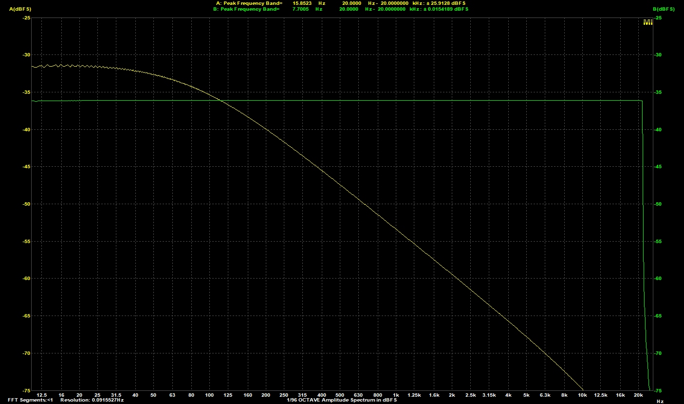
Here is the response at clipping for 18Hz which is 4.8Vpp (notice that the 80Hz first order low pass is active):


Bass Channel Spectrum at Clipping 18Hz.jpg


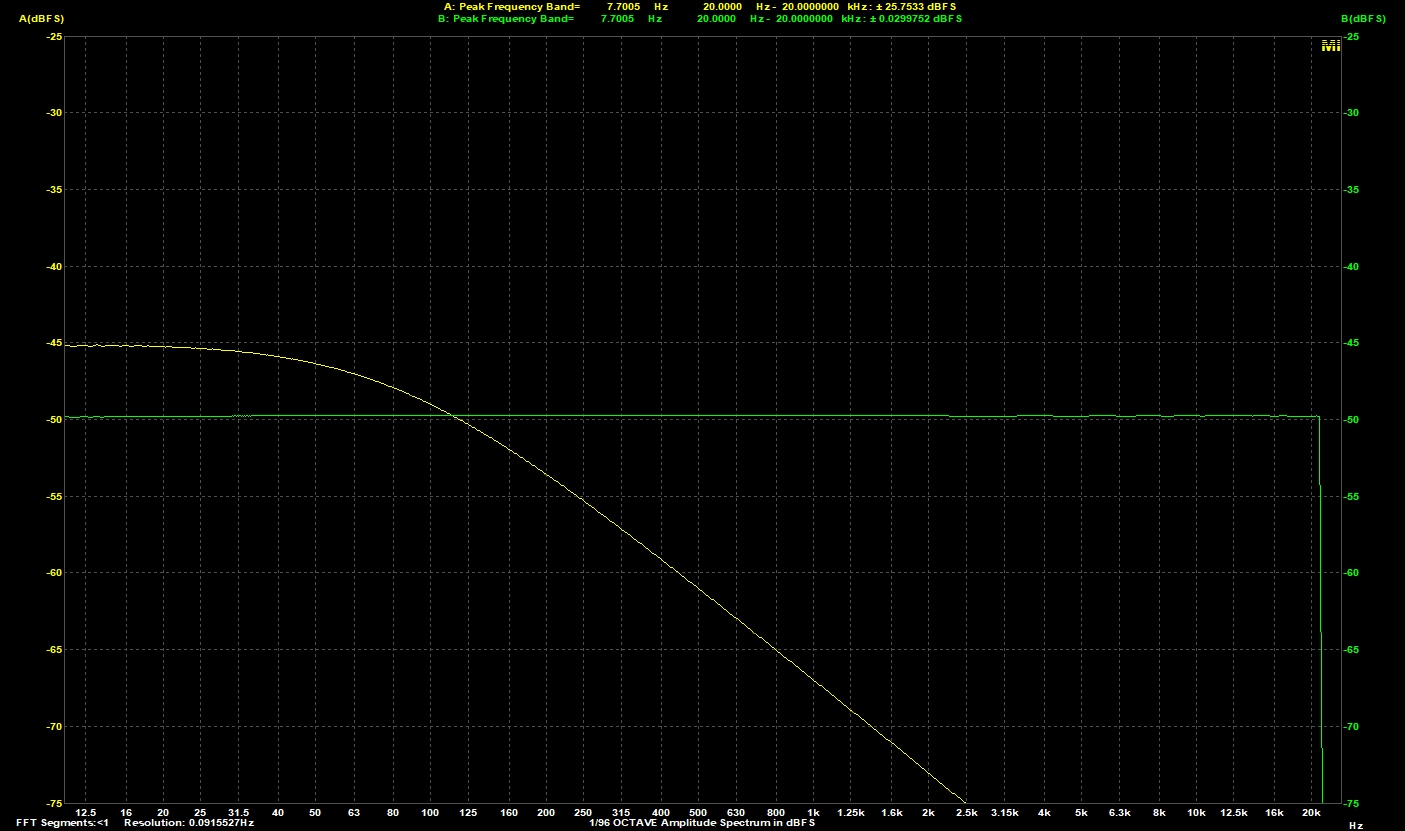
Likewise, this is for a more sedate 1Vpp into 1R:


Bass Channel Spectrum at 1Vpp.jpg


09-08-2019 Post does not mapped to Knowledge Tree
Romy the Cat


Boston, MA
Posts 10,049
Joined on 05-28-2004

Post #: 180
Post ID: 25588
Reply to: 25584
Some perspectives...
Anthony, 
 
Yes, the numbers you got are closed to what I expected they shopped be. Frankly the only concern we have is the Channel A. The in-room response down to 18Hz is good and trust me there is a LOT of musical content in that 18-30Hz. A few things I would like you to understand technically to interpret the numbers you get. 
 
First, your measurements again the “appropriate load resistor” has very little practical meaning. The drivers is a dynamic system that has impedance not resistance and the impedance varies with frequency. So, your measurement against 1R might be accurate for 30.5Hz but might not be accurate at 24.7Hz. So, the proper number at which the clipping might take place would be observable at the real load, or the real driver(s) you use. Then there is a definition of clipping. The clipping is situation when a channel has no power to drive the driver but power is current and voltage. You should not be concerned about juts clipping but you need to assure a SYMMETRIC clipping against you real driver across the whole range of the channel. You need to connect a scope to the channel output while driving your driver and drive a single frequency from a generator and increase the input voltage. Observe the shape of the sinusoid and as the input voltage rise you will see that the top or bottom of the sinusoid will bet distorted, or clipped, or flatted down. The top of the sinusoid is voltage insufficiency and the bottom of sinusoid is current insufficiency (or vise versa, I do not remember already). So, you objective should be to get the absolutely symmetric clipping point when the current and voltage clip at the same time. Then it means that you get out of you amp the max power again your given load. 
 
Second important aspect is that if you deal with an amplifiers then you need to understand when clipping comes from. If might come from many locations. The PS in driver stage, the coupling (in case transformers use), or the output stage PS, or the OPT and so on… The Milq was designed in a way that the any power restrictions are coming from output transformers, the way how SET should be designed and the DSET topology would take care of that limitation. So, the primary focus of your in the given topology should be the only the Channel A output stage. If looks like you beef up enough inductance in you OPT of the Channel A, which is good, not you need to make sure that you can pump power to the output tube. Here is there is another limitation. The 6C33C is indirectly heated tube and they type of tube as the enter to the operation what grid voltage approaches to bias voltage (class A2 or the mode of grid currents)  then this type of tubes do not do so well and they distort rather hard. The direct heated tubes if you feed them with enough current they can push through a little bit but the indirect heated cannot.  You it should be very important to you that in your case your Channel A as the input voltage goes up the Channel stags in Class A1 and the input voltage in the grid of 6C33C does not rise to the rise voltage. In fact, knowing how the Milq is designed this would be the ONLY measurement that I would care as it ejectively demonstrate the efficiency of you LF speakers projected to the acoustic size of you listening room.  I had  at my site a post where I described the measurements I took and posted my measurements in my room.  Here it is:

http://www.goodsoundclub.com/Forums/ShowPost.aspx?PageIndex=1&postID=6057#6057


"I wish I could score everything for horns." - Richard Wagner. "Our writing equipment takes part in the forming of our thoughts." - Friedrich Nietzsche
Page 9 of 10 (187 items) Select Pages:  « First ... « 6 7 8 9 10 »
Home Page  |  Last 24Hours  | Search  |  SiteMap  | Questions or Problems | Copyright Note
The content of all messages within the Forums Copyright © by authors of the posts