| Search | Login/Register
   Home » Melquiades Amplifier » Single-stage Melquiades vs. DHT amps (398 posts, 19 pages)
  Print Thread | 1st Post |  
Page 18 of 20 (398 items) Select Pages:  « First ... « 16 17 18 19 20 »
   Target    Threads for related reading   Most recent post in related threads   Forum  Replies   Views   Started 
  »  New  DHT driver & input..  Effects of radiation...  Melquiades Amplifier  Forum     25  237802  02-01-2007
  »  New  The one-stage Melquiades...  It's time, what amorphous opt...  Melquiades Amplifier  Forum     74  654914  04-21-2007
  »  New  The single-stage Milq and power Supplies...  Just the tank...  Melquiades Amplifier  Forum     10  95682  05-03-2007
  »  New  The 6E5P tube data...  Bartola Valves: 6e5p beam tetrode SPICE model...  Melquiades Amplifier  Forum     44  463864  07-23-2007
  »  New  6 Channel Version of Super Melquiades..  The first Milq screw up....  Melquiades Amplifier  Forum     131  1202733  08-08-2007
  »  New  My (Amplification + Acoustic System): what is next?..  Macondo and Melquiades in the NEW room....  Audio Discussions  Forum     41  301279  01-10-2008
  »  New  Incorporating active crossovers into DSET..  Thanks...  Melquiades Amplifier  Forum     2  43991  07-22-2008
  »  New  About the life-expectancy of the new production tubes...  Stressing the damn contemporary tubes....  Audio Discussions  Forum     9  89600  12-29-2008
  »  New  Small SET’s bass, besides everything- is it about power..  Importance of OPT and type of tube for SET amp bass per...  Audio Discussions  Forum     4  82722  01-12-2009
  »  New  Macondo: new horizons. A few thoughts in context Zander..  What does make a playback to stop?...  Playback Listening  Forum     9  72238  02-02-2009
  »  New  The period DHT tubes and Swastika..  Maybe there is another solution...  Melquiades Amplifier  Forum     1  27264  04-30-2009
  »  New  Some thoughts about Milq’s MF filter..  High-Pass RL Filter calculator....  Melquiades Amplifier  Forum     2  33396  05-02-2009
  »  New  The DHOFT topology? Do not try it home...  A medley of slow-cooked triodes....  Melquiades Amplifier  Forum     3  46631  05-04-2009
  »  New  Why the tubes shall be the same?..  Not optional anymore?...  Melquiades Amplifier  Forum     7  61912  05-11-2009
  »  New  Valve Technology Timeline..  A good video about tubes making....  Audio Discussions  Forum     5  95304  06-18-2006
  »  New  The DSET perspective examines the Herb Reichert article..  Are you still in Reutlingen, Germany?...  Melquiades Amplifier  Forum     5  93872  07-01-2009
  »  New  About the Critical Audio Tune ™..  “Critical Audio Tune” bay-leave in the soup......  Playback Listening  Forum     5  50593  08-29-2009
  »  New  A full-range quality-triode? Does Size mater?..  A full-range quality-triode? Does Size mater?...  Melquiades Amplifier  Forum     0  16917  12-02-2009
  »  New  About Stupid Dynamic..  Misplaced dynamics....  Playback Listening  Forum     1  20943  08-21-2011
06-17-2009 Post does not mapped to Knowledge Tree
cv
Derby, United Kingdom
Posts 173
Joined on 09-15-2004

Post #: 341
Post ID: 10809
Reply to: 10806
The 10Y...and bye bye Newton
fiogf49gjkf0d
Hello Romy,
I've only heard the 801 in class A2, but I can easily imagine that the 10Y or 801 with nickel output would offer the purest possible sound in the 1k-10k range, such that it is the S2's true voice you are hearing. It's something I'm going to pursue when I have time/funds...

Alas I do think that your existing amp platform (i.e. B+ voltages) is not optimal for 10Y; the DC coupling would be out etc and this may well swamp the differences between tubes.

Anyway, whilst you do have the urge to experiment, you really, really should try a tapped filter choke at the front for gain adjustment instead of the attenuator at the S2.

If it's not too much a departure from the subject of the thread, I'm a little surprised to see the back of the "Newton bias" scheme; does the 6E5p still retain its special qualities in this application with the more pedestrian bias arrangement here (IIRC the Newton scheme's primary benefits were at LF?), or might it now be worth experimenting with a filament-biased DHT at the front (and dropping some gain in the process...)? You might ask Dave if he knows of any 9-pin DHTs with mu of about 18 and Ri of about 1k... or have me send some old Limey tubes - begging your pardon, sire - valves to try...

I do appreciate that this amounts to untargeted experimentation and may be an intellectual exercise for the most part, but it would form a consistent continuation of the amp's development path.

Cheers
cv
06-17-2009 Post does not mapped to Knowledge Tree
Romy the Cat


Boston, MA
Posts 10,049
Joined on 05-28-2004

Post #: 342
Post ID: 10812
Reply to: 10809
The commentaries about everything.
fiogf49gjkf0d

 cv wrote:
I've only heard the 801 in class A2, but I can easily imagine that the 10Y or 801 with nickel output would offer the purest possible sound in the 1k-10k range, such that it is the S2's true voice you are hearing. It's something I'm going to pursue when I have time/funds... Alas I do think that your existing amp platform (i.e. B+ voltages) is not optimal for 10Y; the DC coupling would be out etc and this may well swamp the differences between tubes.

Yep, this is one of the reasons why I do not do it. I have some very cool 10Y but the plug-and-play with 10Y will not work with my current Milq platform. If I can go away with 6.3V on filament then I will not be able to go away with 410V driving 10V. That would bring another B+ supply and so on. People have no idea how much I hate to do that DIY soldering crap! The second reason, probably the biggest one that for now I do not feel frustrated with the result I got from 2A3/RN604/YO186/45. My rules of the engagement no one cancels yet:

http://www.romythecat.com/Forums/ShowPost.aspx?PostID=432

 cv wrote:
Anyway, whilst you do have the urge to experiment, you really, really should try a tapped filter choke at the front for gain adjustment instead of the attenuator at the S2.

This is a good one. I have a number of conversations with David about it. I do not exactly subscribe the idea of his tapped filter chokes and autoformers. In fact I feel that conceptually they are faulty. In regular resistive attenuator a signal flows across a resistor that is more of less free from any none-linearity. In a tapped chokes the attention happens via inductive resistance where the whole series signal flows across none-linear galvanic element. So, in theory I feel that restive attenuation is less devastating. I never used autoformers and frankly I have no motivations to do it. David, argues that a magnetic element is better than resistive and is willing to prove it to me by sending to me his speaker-level autoformers. I a very skeptical and I would rather to pay for a very high resolution (1/6dB) resistive speaker-level steps-attenuator with constant impedance. I am contemplating to commission the 16R LPAD if I find a right person….

 cv wrote:
If it's not too much a departure from the subject of the thread, I'm a little surprised to see the back of the "Newton bias" scheme; does the 6E5p still retain its special qualities in this application with the more pedestrian bias arrangement here (IIRC the Newton scheme's primary benefits were at LF?), or might it now be worth experimenting with a filament-biased DHT at the front (and dropping some gain in the process...)?

Good point, I have thought about it as well. The 6E5P with "Newton Bias scheme” is not a panacea but a solution with well defined objective: to eliminate any explicit capacitor from a stage. How would you bias a tube? A buttery in grid or cathode do not sound right, not to mention that they are in a way the “capacitors”. A fix bias would imply a coupling cap or transformer, all versions of cathode bias would imply a cap in cathode. What you call the “Newton Bias” (actually the Newton Bias was another notion and it had nothing to do with Milq – that was a bias in Zaratustra amp) is affective way to bias with signal flows across juts a resistor – in my book the least damaging element. In the MF channel you see that I return to cathode bias but it was different. Since the objective was to lower the gain of my driver stage the 6E5P is use with no bypassing cathode cap –just a series resistor -means no negative problems in my book. 

Another point that I make is that I know how the 6E5P sounds with no caps and “Newton Bias”. I presume that it might be another application that might be fine but I would like do not spend time to evaluate many other options. In Milq tweeter channel of the “Newton Bias” on 6E5P in my view is not good idea at all as the 6E5P is quite capacitive bitch but what is the alternative? I have a single gain stage with a single resistor in a series signal path – what might be more kosher then this? I would like to have less capacitive tube with more gain and more power for HF channel, however….

 cv wrote:
You might ask Dave if he knows of any 9-pin DHTs with mu of about 18 and Ri of about 1k... or have me send some old Limey tubes - begging your pardon, sire - valves to try...

I did ask about that type of tube before. Any interesting DHT candidates with high gain have too high plate impedance. If I find one that can do 20 times gain, have plate of 500R-700R and able to care 5W-7W on plate then I would go for one DHT stage. Unfortunately I do not know such a tube, with exception of high power transmitting tube that would run at 1kV and that I do not need.

The Cat


"I wish I could score everything for horns." - Richard Wagner. "Our writing equipment takes part in the forming of our thoughts." - Friedrich Nietzsche
06-17-2009 Post does not mapped to Knowledge Tree
cv
Derby, United Kingdom
Posts 173
Joined on 09-15-2004

Post #: 343
Post ID: 10813
Reply to: 10812
Driver tube and biasing
fiogf49gjkf0d
Allo

On the matter of the DHT having a plate resistance of 500-700... you do realise that running the 6E5p with an unbypassed cathode resistor is giving you an effective Rp of about 12k, right? The formula is, IIRC, Rp + (mu+1)Rk.

Given that 12k seems to be ok for driving the output stage, I had in mind the LP2 which has a mu of 15, an Rp of about 5k, 2V heater. Alternatively, there's the P2, which is half the mu and Rp.

The idea was to use filament bias - this is where you put the heater and cathode bias resistor in series, so that the bias is derived from the heater current. It's wasteful of power, but it does mean you can use a very, very small cathode resistor. Eg if the tube needs -6V of bias and has a 2V / 0.2A heater, then you have an 8V heater supply and a 30 ohm cathode resistor...

Regarding the inductive attenuator - in using an LR filter at the input, the series R will give the inductor a chance to express any non-linearities in voltage terms. With a 6db attenuator, the signal is tapped half-way through the core, so I can almost visualise cancellation of non-linearities in each half...whatever they might be. Then there is also the benefit of the driver tube seeing 1/4 of the filter R.

In any case, just some food for thought, lest you do identify something lacking in the sound down the line.
cheers
cv
06-17-2009 Post does not mapped to Knowledge Tree
nl
Posts 14
Joined on 06-15-2008

Post #: 344
Post ID: 10814
Reply to: 10813
DHT drivers
fiogf49gjkf0d
Why do we use DHT tubes? it is not because of their technical specifications. They have low transconductance, a problematic direct filament, and they cost a lot.
Obviously, it is because of their sound. Some people like it and some people don't.
The DHT's low gain makes a driver stage necessary.
In Romy's case, I would suggest experimenting with various driver stages. The primary quality is how it sounds -- how it combines with the DHT sound to make an appealing overall result.
Many, many, many experiments have been done regarding different driver stages.
People keep coming back to the 6sn7 over and over again. It is a good sounding tube. They try the 9-pin series (12ax7), high-gm drivers (417a), pentodes (C3m), etc. etc. and come back to the lowly 6sn7.
Why are we experimenting with DHTs at all here? It is because of the possibility of a different sound character than the 6E5P. Using a 6E5P as a driver, with DHT output, compared to a 6E5P alone, will tend to result in "something that sounds like a 6E5P but with DHT coloration, and the fuzzyness caused by a second stage."
Thus, it doesn't make a lot of sense to me to keep the 6E5P as a driver tube. Why not try something else?
I would suggest a 6SN7 or possibly a signal DHT like a 26, 112, 01A, 30, etc. etc. Direct coupled with resistor load (as already exists) is fine.
Some people like the combo of a high-gm tube like 417, 6H30, 6S45, etc. etc. as a driver tube. Other people find them hard, glassy, and not emotionally involving -- the typical complaints of the high-gm series.
The main advantage is that they allow the elimination of a gain stage. Also, they provide a rather low Rp to drive the output tube harder.
However, in this case, there is not much need for gain, so whether you use a 6H30 or a 6SN7 or a 26, you end up with two stages anyway.
The second thing I would suggest (again) is to try your DHT amp running the large horn (600hz up) as far up as it will go -- ie no lowpass filter. That should give a better idea of the overall sound quality of the DHT amp without having to make two to run both horns simultaneously.

06-17-2009 Post does not mapped to Knowledge Tree
Romy the Cat


Boston, MA
Posts 10,049
Joined on 05-28-2004

Post #: 345
Post ID: 10817
Reply to: 10814
The ideas are worth trying?
fiogf49gjkf0d

 cv wrote:
On the matter of the DHT having a plate resistance of 500-700... you do realise that running the 6E5p with an unbypassed cathode resistor is giving you an effective Rp of about 12k, right? The formula is, IIRC, Rp + (mu+1)Rk.

The DHT that I meant was a candidate for a single stage gain with DHT. To find a DHT to substitute just my 6E5P driver is not too difficult.

 cv wrote:
Regarding the inductive attenuator - in using an LR filter at the input, the series R will give the inductor a chance to express any non-linearities in voltage terms. With a 6db attenuator, the signal is tapped half-way through the core, so I can almost visualise cancellation of non-linearities in each half...whatever they might be. Then there is also the benefit of the driver tube seeing 1/4 of the filter R.

… and the part of the signal that need to be NOT attenuated still will be flowing through the part of the coil. The flowing across the DCR of the tap is not a big deal but it is INSIDE of a choke and theoretically it is influenced by all issues of magnetic non-linearity.   Do not forget that to the magnetic non-linearity exposed the part of the signal the shunted to ground AND the part of the signal that shall flow top load with no impact. This is my theoretical beef with the idea of magnetic attenuation.

 nl wrote:
Why do we use DHT tubes?

You mean the driver DHT tubes?  Yes, it might be an interning idea but at this point I see no need.

 nl wrote:
In Romy's case, I would suggest experimenting with various driver stages. The primary quality is how it sounds -- how it combines with the DHT sound to make an appealing overall result.

nl, what in your view might be the “appealing overall result” that you feel might be accomplished by substitution of my driver with DHT? I understand that you never heard the sound I get from 6E5P and I never used the DHT driver and therefore there are no points of reference, still what would you your hypoteti9cal assumptions?

 nl wrote:
Why are we experimenting with DHTs at all here? It is because of the possibility of a different sound character than the 6E5P.

I do not looking for “different sound character”. That is what most of the DIYers do not get. I am looking for the very specific character of sound that I know, understand and comprehend. The differences that many “soldering people” are getting out there are completely irrelevant to me as I very seldomly experienced that DIY build any “tailored” or sensible sound. it does not mean that I shall not experiment with DHT drivers but it means that a promise of “ the different sounds” is not something that motivates me.

 nl wrote:
Thus, it doesn't make a lot of sense to me to keep the 6E5P as a driver tube. Why not try something else? I would suggest a 6SN7 or possibly a signal DHT like a 26, 112, 01A, 30, etc. etc. Direct coupled with resistor load (as already exists) is fine.
Some people like the combo of a high-gm tube like 417, 6H30, 6S45, etc. etc. as a driver tube. Other people find them hard, glassy, and not emotionally involving -- the typical complaints of the high-gm series.
The main advantage is that they allow the elimination of a gain stage. Also, they provide a rather low Rp to drive the output tube harder.

Interesting, those people who “like” or “do not like” something about the DHT drivers, do they make their judgments in context of full-range SETs or in context of the narrow- band DSETs?

 nl wrote:
The second thing I would suggest (again) is to try your DHT amp running the large horn (600hz up) as far up as it will go -- ie no lowpass filter. That should give a better idea of the overall sound quality of the DHT amp without having to make two to run both horns simultaneously.

That is interning as I thigh about it myself when I started to use my YO186. The YO186 has VERY lucrative lower range and it might be fun to expose it to my upperbass horn. I do not know about the run the upperbass with no lowpass filter but the notion to try YO186 full-range very much crossed my mind. A local guy snatched my prototyping San Audio amp otherwise I would put the YO186 in full-range use and would try to drive with it different things. I still do not know if it will be able compete with 6C33C as the 6C33C drivers my upperbass with VERY idle plate. The DHT tubes would not have power to idle plates too much. If I put the YO186 with 45:1 transformer then it will suffocate to drive my upperbass driver.  Still, the idea is worth trying…

The Cat


"I wish I could score everything for horns." - Richard Wagner. "Our writing equipment takes part in the forming of our thoughts." - Friedrich Nietzsche
06-21-2009 Post does not mapped to Knowledge Tree
Romy the Cat


Boston, MA
Posts 10,049
Joined on 05-28-2004

Post #: 346
Post ID: 10870
Reply to: 10806
A question about the polishing the things….
fiogf49gjkf0d

 floobydust wrote:
Paul,
I suppose that new vs old between the 45 and RE604 could account for some differences, but it's more of an "apples to oranges" comparison. Pushing the 45 beyond it's ratings is not a great idea... especially the cathode current as it will certainly shorten it's life... I always run the 45 around 34-36ma and never any more. You can run the plate a bit beyond 10-watts (the final revised rating) provided you have adequate airflow and keep the cathode current down.

floobydust or whoever,

I have a question. I have a situation in here that needed a minor correction. It might be left as is but still I would like to fix it. Sine I have my hard is set not at 45 tube I would like them to run very much equal. My amps not have rig and left channel run ~5mA different. With the same tube the left amp has (K-G-A) 191V-155V-407V and the right amp has 198V-161V-407V. That makes left amp to have 5mA less currant then right and I would like to make them the same (with the same tube). I can match the DC that comes from driver tube (155V vs. 161V) but the voltage drop on my cathode is different, probably due to the not exact value of the power resistor.

So, I probably will not remount it but will put a large resistor in parallel to the higher one and will make the cathode resistors the same. My question is: how much you advise to drive my 45. Usually people think how to get more power but I do not need power. So, I do not have the “best” operation point that would assure the most power but I rather can driver it wherever I wish. So, how much shell I wish?

The 45 is 10W tube. I have 407V-191V or 208V on the tube and I run it at 35mA and 40mA or at 7.5W and 8.3W. Where do you fee; it the good point to me settle: 35mA and 40mA? Sonically I hear no deference…

The Cat


"I wish I could score everything for horns." - Richard Wagner. "Our writing equipment takes part in the forming of our thoughts." - Friedrich Nietzsche
06-21-2009 Post does not mapped to Knowledge Tree
Paul S
San Diego, California, USA
Posts 2,570
Joined on 10-12-2006

Post #: 347
Post ID: 10873
Reply to: 10870
The Particular Tube, I'm afraid...
fiogf49gjkf0d
Romy, it sucks, but the different good DHT output tubes seem to want trimming to deliver their best.  IMO, the ideal thing would be a quiet way to do this for both channels, not just to match channels but to get the best sound from the particular tube.  I do not mean it in the usual hokey sense when I say I think you will find that you have created a sort of musical instrument that is very nuanced and very responsive, also giving noticibly varied response to its "input".

I used to go through piles of resistors while trimming those things.

Best regards,
Paul S
06-22-2009 Post does not mapped to Knowledge Tree
floobydust


currently roaming the US
Posts 62
Joined on 01-19-2009

Post #: 348
Post ID: 10874
Reply to: 10870
Driving the 45... cathode first
fiogf49gjkf0d
 Hi Romy,

 The final ratings on later ST-style glass 45s was 10 watts on the plate and 300 volts cathode to plate max. Recommended bias current is between 34-36ma max. Short answer... I prefer no more than 34ma on the 45 cathode. It's a coated cathode type on a thin filament wire and pushing them will run them down quicker. If you can manage 35ma and match the set I'd say you're good to go. The only problem is your available supply voltage. As you're "backing into" a set of fixed parameters (plate voltage supply is already defined), you might need to alter your driver operating point to get the 45 in this range and maintain optimal performance. Of course, you know better than I about the driver stage and where it's optimal operating point is. I would do some (bias) trimming on the driver stage first and see if you can reduce the 45 idle current to no more than 35ma while keeping the driver stage operating properly. If not, you might end up trimming the cathode resistor to get there.

 Regards, KM


... just because you're paranoid, it doesn't mean they're not after you ...
06-22-2009 Post does not mapped to Knowledge Tree
Paul S
San Diego, California, USA
Posts 2,570
Joined on 10-12-2006

Post #: 349
Post ID: 10880
Reply to: 10874
ST or Globe; old or new...
fiogf49gjkf0d
Sorry, I was not clear (as usual...).  I meant trimming per individual 45 tube type, not re-trimming for each individual 45 tube of a particular type.  I doubt you will want to run your old globes the same as you run your new STs, etc.

And since you are focusing on the 45, maybe you can bring yourself to yank out the extra, swap-o-matic stuff now?

As KM observes, the way your PS (delivery) is set up may limit your easily-available range of worthy operating points, and that might wind up helping you decide on which particular 45 you use.  And it may yet come to pass that you get curious and re-visit your driver, anyway, as you get more familiar with your particular choice of 45.

Best regards,
Paul s
06-22-2009 Post does not mapped to Knowledge Tree
Romy the Cat


Boston, MA
Posts 10,049
Joined on 05-28-2004

Post #: 350
Post ID: 10881
Reply to: 10874
Whatever sticks to the wall as an operation point in my case?
fiogf49gjkf0d

 floobydust wrote:
 The final ratings on later ST-style glass 45s was 10 watts on the plate and 300 volts cathode to plate max. Recommended bias current is between 34-36ma max. Short answer... I prefer no more than 34ma on the 45 cathode. It's a coated cathode type on a thin filament wire and pushing them will run them down quicker. If you can manage 35ma and match the set I'd say you're good to go. The only problem is your available supply voltage. As you're "backing into" a set of fixed parameters (plate voltage supply is already defined), you might need to alter your driver operating point to get the 45 in this range and maintain optimal performance. Of course, you know better than I about the driver stage and where it's optimal operating point is. I would do some (bias) trimming on the driver stage first and see if you can reduce the 45 idle current to no more than 35ma while keeping the driver stage operating properly. If not, you might end up trimming the cathode resistor to get there.

Floobydust,

I hear what you are saying but I do not know if I agree with you. It kind of odd – I ask advice and I disagree with the advice but it is not that disagrees but rather it does not conform to my view of “common since”. Let me to lay down my view, perhaps my view is inaccurate and you will be able to point out where I am wrong. 

The source of my disagreement is 35mA as some time of absolute number that has own meaning. Yes, the typical operation of 45 reportedly 250V and 35mA that makes 8.7W. Furthermore I presume that it is high possible that you guys who are experienced with this tube found that at this operation point the 45 does the best.  Highly possible and I would not debate it. However, let remind to each other that a proper operation point is a subject of voltage, current, load and the most important from my point of view – a symmetrical clipping under the given voltage, current and load. Only with context of the symmetrical clipping the tube give up max power and experience no voltage and no current starvation under any signal amplitude (until it clips).

Now, let see what happens in my case. Firs my channel runs no LF and it is DSET. In classic SET configuration power is derivative of LF as inductance dies first. In case of SET employed as DSET and has not LF the consideration of power as current vs. voltage are not there. My MF amp would hardly clip by power of output stage but rather by overdriving the stage very deep into A2 and by clipping the driver stage. If so the symmetrical clipping of the output stage might not be a subject and therefore is might not be the only right operation point. In my case I run the tube at 208V and at 35mA and 40mA or at 7.5W and 8.3W, what is near the same plate dissipation as 250V/35mA (8.7W). If I do not have objective to get max power from the tube then why 208V/40mA might be worse than 250V/35mA? You suggests that “it's a coated cathode type on a thin filament wire and pushing them will run them down” but current does not burn cathode, I presume temperature does as a derivative of power. It you have a fuse that goes off at 1A and 120V then it will not go off at 1A and 12V. This is my argument, I do not know if I right but it makes “common sense” to me.

There is another subject. The common practice to use 45 is to load it against 6KOhm. I am loading it against 9.5K and will be soon against 11K. This is 2 times idler load and I am sure that power-perfect operation point will be moved from 250V/35mA. So, do I need to worry about 40mA in my case or I might use whatever stick to the wall as long it is within 8W?

The caT


"I wish I could score everything for horns." - Richard Wagner. "Our writing equipment takes part in the forming of our thoughts." - Friedrich Nietzsche
06-22-2009 Post does not mapped to Knowledge Tree
Romy the Cat


Boston, MA
Posts 10,049
Joined on 05-28-2004

Post #: 351
Post ID: 10885
Reply to: 10765
The attenuating crap in secondary.
fiogf49gjkf0d

I made today an experiment trying to remove the wirewound LPAD attenuator from the MF’s channel secondary. I was VERY surprised how much better it was with no attenuator. I knew that it was not optimum but the degree it ruined sound was a big surprised to me.

The attenuator tine out rolled of HF quite aggressively, I did not use the MF without attenuator sine I got the last 25:1 Slagle’s coil and it was a mistake. With no attenuator the S2 runs much high – exactly what I would like. At that time I was using my 4V tubes that have ~3-4dB more gain then my 45s. With 45 I need to attenuate just 1dB…  So, I took 1.5R Mills non-inductive resistor and put it sire s with S2 driver. Not even a divider but juts a resistor. I feel that in context of HF driver and when a resistor is a fraction of VC impedance it is a legitimate way to do the things. There is not contra-current from compression drivers (no exertion) and dumping is not affected. Not to mention that my driver sits behind the 3.2KHz filter… So, with 1.5R resistor I hit the reference gains at 1000Hz but at 12kHz I need 1.5dB down in relation to this reference level!!! Playing the playback with MF at minus 1dB – the level that was fine with attenuator- make the playback bright like hell. Who could believe that the attenuator would eat so much?!!!

Also, adding 2-3R with series with S2 I will idle the 45 even more, loading it to 12KOhm-13KOhm… I need to order some very “fast” and very none-inductive power resistors… talking with those people…

http://www.texascomponents.com/pdf/tx221.pdf

The Cat


"I wish I could score everything for horns." - Richard Wagner. "Our writing equipment takes part in the forming of our thoughts." - Friedrich Nietzsche
06-22-2009 Post does not mapped to Knowledge Tree
floobydust


currently roaming the US
Posts 62
Joined on 01-19-2009

Post #: 352
Post ID: 10887
Reply to: 10881
Operating points and cathode current
fiogf49gjkf0d
 Romy,

 I don't think we're in any major disagreement. It's clear you have a good operating point and performance indicates this as well. I did a "normalized" model of this with the 2A3 and 45 and it specs well. All I'm suggesting is that all early and final specifications for the 45 showed a maximum recommended cathode current of 36ma in any and all operating modes. As a result, I simply think there is a higher risk of running the tubes down faster. I've seen some older 45 tubes where the getter is used up a fair amount and there is some brown hazing on the top inside of the glass. I would suspect this to be a result of running them too hot which resulted in some internal contamination. As all 45 tubes were made before the mid-1940's, it's uncertain how pure and/or advanced some of the cathode coatings were. For my own reference, I've put more than 1000 hours on a NOS pair of Zenith branded (and sealed boxes) 45 tubes in my current amps and they are still maintaining their initial performance. They are made by Sylvania and of my preferred internal construction.

 There is one other 45 tube you might look into... just a wild shot. EML make a 45 solid plate and a mesh plate. I have a pair of the solid plate and they are huge. I don't consider them a real 45, but one thing is for sure... they are built like a tank (butt ugly too) and actually sound good at 40ma cathode current, use less and you notice it. I changed my amps specifically to run these for some listening tests. Ultimately, I find the EML to be too sensitive to mechanical exitation and not quite as neutral sounding as the real 45 and went back to my NOS Zenith/Sylvania pair (and back to 34ma). Still, maybe it would perform better in your circuit.

 As for load impedance, most of the operating points I've calculated (via plate curves, a straight edge and a calculator) and tried in practice confirmed that, at least in my application, a 5K load seems quite optimal at the voltage and current I'm using. Increasing to 7K resulted in a loss of signal linearity at higher power before clipping. Dropping the impedance would get some additional power, but only if you run the current up as well. Again, your application is pretty much doing what you want it to. Only comment is that (as you know) you'll loose some power as the load impedance goes up. You can easily go to 10 watts on the plate as you seem to have adequate airflow, but with your currently available plate voltage I would look to limit the cathode current more to spec. If you're happy with the 40ma current... I won't argue. I would be highly interested to see what your view of tube life is if you get to a point where you think they are losing performance. Likewise, if you opt to drop the current down, again... more feedback on your observations.

 Regards, KM


... just because you're paranoid, it doesn't mean they're not after you ...
06-22-2009 Post does not mapped to Knowledge Tree
Paul S
San Diego, California, USA
Posts 2,570
Joined on 10-12-2006

Post #: 353
Post ID: 10890
Reply to: 10885
The Burgeoning Opportunities!
fiogf49gjkf0d

The hell of it is that you will probably have to peck away at working out your plate and cathode OPs at the same time, since measuring resulting values is a lot easier than actually predicting them.  Or, you will probably have to do this if you want to control wattage, anyway.  Just keep close track of all values and related impressions of sound - or at least sound trends - so you can subsequently repeat or avoid values/settings, etc., apropos.

And there's still more fun ahead!  I have noticed clear differences in sound when staying with the same values but changing only resistor type and/or brand.  Yippee!

I tend to like the "non-inductive" wire wound for plates and the "harder" tantalums for cathodes.  In any case, try for yourself and check out the differences.

As for speaker-level resistors, you could just use cement type, for all that, or try these:  http://www.duelundaudio.com/Resistors.asp

Best regards,
Paul S

06-22-2009 Post does not mapped to Knowledge Tree
Romy the Cat


Boston, MA
Posts 10,049
Joined on 05-28-2004

Post #: 354
Post ID: 10891
Reply to: 10890
Actually it is not so simple.
fiogf49gjkf0d

After all, I faced a problem where I did not expect it. The MF channel with no wirewound LPAD attenuator sounds more extended but at the same time not all of that extra HF too useful. In fact, what I hear is that with the series resistor Sound has in a way “superfluous brightness” that I do not really like. I did not have the right volume resistor to add an extra .5dB and I used other resistors. It was shocking how different and how much auditable the different resistors sound in this application. In fact at voice coil level it is order and order of magnitude more auditable then if they were the resistors were at line level. I had no idea…. Paul, that for the link, I did not even know that there is a special market for the resistors in this position. At this point I would love do not have any resistors in the secondary...

The Cat


"I wish I could score everything for horns." - Richard Wagner. "Our writing equipment takes part in the forming of our thoughts." - Friedrich Nietzsche
06-23-2009 Post does not mapped to Knowledge Tree
cv
Derby, United Kingdom
Posts 173
Joined on 09-15-2004

Post #: 355
Post ID: 10893
Reply to: 10891
Resistors at the front
fiogf49gjkf0d
How about shunting the 1H choke with 180K or so and changing the 20k to 22k5.... that's a rough calc (should redo for standard values)... will keep the x/o point the same and eat up a decibel...


06-23-2009 Post does not mapped to Knowledge Tree
Romy the Cat


Boston, MA
Posts 10,049
Joined on 05-28-2004

Post #: 356
Post ID: 10894
Reply to: 10891
A minor alternation of a position
fiogf49gjkf0d
The events of the last 3 days are incredibly stupid, incredibly interesting and very educational. During the last few days I have discovered some very interesting phenomena, ok might be no a phenomena but a behavior, that would quite alter many of my conclusions expressed in this thread, and in few other threads. I will probably post a summary in a few days about my latest observation when I will have a complete picture.

The Cat


"I wish I could score everything for horns." - Richard Wagner. "Our writing equipment takes part in the forming of our thoughts." - Friedrich Nietzsche
06-26-2009 Post does not mapped to Knowledge Tree
Romy the Cat


Boston, MA
Posts 10,049
Joined on 05-28-2004

Post #: 357
Post ID: 10915
Reply to: 10894
The era of enlightenment.
fiogf49gjkf0d

 Romy the Cat wrote:
The events of the last 3 days are incredibly stupid, incredibly interesting and very educational. During the last few days I have discovered some very interesting phenomena, ok might be no a phenomena but a behavior, that would quite alter many of my conclusions expressed in this thread, and in few other threads. I will probably post a summary in a few days about my latest observation when I will have a complete picture.
It was very interesting as educational. Everything started from the fact that I was superbly happy and comfortable with the sound I was getting with my late DSET with 45 arrangements on MF. So, I figured – I can make it a perm fix and decided to get rid the LPAD before the Vitavox. I replaced the LPAD with 2R Mills resistor one night and decided that it is how it will be permanently.

Next day I got home, turn my audio and it was not just bad electricity day it was probably the worst sound I had for a long time. It was not just bright it was ribs-twisting bright. Also, there was the “character” of those heights. The character of sound was very odd. It was what I call the “sound of the autumn leafs” – it sort of over-burned sound with almost inverted HF, in away remind the sound of BlackGate capacitors that were “just a few month ago” installed. It is very effective sound with a lot of bite into edge of the notes but I very much hate this sound. I was checking everything in playback (the PP2000 was the first to blame), everything was fine but on the back of my mind I felt that it sounded like my MF driver was too idle as it was the very first sign of inadequate load. Yesterday it was perfect, today is unambiguous crap, the quality of electrician is stable – so what went wrong? I could blame the Alfa-rays storm from Sun but I concentrated my attention on the 2R resistor I changed last night.

Now, I replaced the shitty wirewound LPAD with very high quality Milles non-inductive resistor – how wring would it be? Sure, I put the LPAD back and the sound was fixed immediately. OK, I decided the 2R Milles resistor it just too “bad” I need something better. So, being a blind fool who I have ordered the best imaginable 2R resistor out there…

Then I asked myself: why I have those problems? The sound of “bad” resistor shall not affect sound in this way. I had 5 of 6 different types of resistors and all of them hugely change sound. It not supposes to to be this way first of all and second of all why the result so much reminds me the too idle plate load? Further research indicated that I was right – it has nothing to do with resistors.

Thos of you who use large compression drivers with metal diaphragms, and particularly the Vitavox S2 driver, know how the drivers behave when you decrease load. They are getting the “lower distortion” and better transients and then at some point the HF knee of the driver begin to sound like they disintegrated and driver pick some rusty or sandy texture.  What happens is the diaphragm loose the critical dumping by the plate impedance and the cone begin to break-up more auditably. A few years back, what I was playing with Vitavox S2 driver with original metal cones and metal suspension (the configuration that as very sever “sandy texture”) I was trying to cure the problem with a very small low pass filter at 25-40kHz. To a degree it helped than, so I was wondering if in my current situation I deal not with the “bad” and “good” sounding resistors but with the pure low pass filter in my OPT secondary. So, I began to look deeper into the nature of inductance of my resistors.

The working hypothesis was that I might over idle my tube plate and then “correct” the “sound of the autumn leafs” with low-passing sound with LPAD’s inductance. When I put the none-inductive “bad sounding Mills” into game instead of LPAD then I actually have no low-pas and hear sound as it is – too idling plate. I knew that my wirewound LPAD is in away a mind indictor –what the values we are talking about? I was not able to measure LPAD inductance with my inductive bridge as it run at too low frequency.   I took my FM tuner sweep-generator that runs at 100mHz and blew the LPAD with it. The thing was almost not conductive!!! The most horrible was not even the high inductance of the thing but the fact that inductance was almost doubling wish impedance. I did not make a good inductive bridge to get exact numbers but I was OK to get relative numbers.  What I end up was the LPAD in 2R retting had approximately .270millinery and approximately .480millihenry at 6R. The 2R Millls had approximately .035millihenry, the wirewound Vishay-Dale RH had .015millihenry and the military wirewound non-inductive NH version of Vishay-Dale had around .0025millihenry. The crazy Vishay S-102, that is not wirewound but metal file and in addition made with many anti- inductive techniques have whopping .00015millihenry…

Ok, I have 16R load and LPAD at 2R and .270millinery, so had a filter at approximately 9000Hz. That what I need to run 45 tube to attenuate 1dB. With YO184/RE604 I need to attenuate ~3-4 db and with this attenuation I run ~.5millinery. With this inductance I have a filter at 5000Hz. How you understand why I felt that my 45 tube run much higher and cleaner then my 4V tubes? This kind of explains to me a phenomenon that I was not a able to explain to myself. When I was running the YO184 for a first time I was very pleased but then when I put the LPAD into the game and was running YO184 through the LPAD I found that it was “not too extended”. What was in particularly interesting that when I was listening the only one MF channel with YO184 then I did not feel any HF deficiency but did feel it when I was listening the same YO184 integrated into Macondo.  Now it is understandable why – because integrated in Macondo I run my 4 tubes with 3-4dB LPAD attenuation and 5000Hz low-pass filter from the wirewound inductance.

So, to summarize what I was doing: I have an attenuator that very aggressively rolled of HF with attenuator. OK, that all explains my former silliness but what would be the solution to go forward.

First I re-listened all my tube options with no LPAD. With LPAD the 25:1 does well if the attenuation was no more than 1dB. This way the presumably the low-passing coming from the attenuation helped to “fix” the S2’s over-idle fuzziness.  Although the result was very good – in fact seriously good with 45 tube (as it demanded juts 1dB attenuation that was a perfect match in my case). Still I did not feel that it was right way to go. Fists I did not what to have explicit S2 curing inductor   and second I would like to be able to add and reduce the S2’s volume in Macondo. Others ways to do it had to be found. The attenuation at input I discarded as I need a continue attenuation and my high-pass input filter would not allow me to do it. To put the attenuation between the stages did not appear kosher to me as well. So, since the inductors connected in parallel crate the sumizing inductance less than any one of the parallel inductors I asked myself what not to shunt the LPAD with ultra-low inductance and high impedance. This way the high impedance will not impact the LPAD maintains the fix and stable load for my tube and the ultra-low inductance will null out the inductance of the wirewound coils in my LPAD. So, I took a pair of Vishay S-102 resistors and bridged each side of the LPAD. The result was wonderful, the LPAD rolled of volume but maintained the frequency range. The most important was that now my 4V tube, while they were 4dB attenuated, got very nice HF extension. Hallelujah!

With LPAD’s inductive influence contained the 25:1 load sound too idle and I feel that 20:1 would be more suitable load. (The 25:1 works well ONLY with inductive low-pass). Thankfully I still have the Slagle’s 20:1 coil and I put it back. It is what I play now. At this “no inductive” setting my views about the 2A3, 45 and the YO184/RE604 are slightly altered. The 45 still have the super clean and much extended HF but 2A3 and my 4V tube this time do not loose so dramatically in HF department as they did with 4dB attenuation and inductive low-pass. The debate between the 45 and 4V tube not is not around the HF anymore but rather more about the accents. The 45 is still “cleaner” in upper-end but it is restrained in tonal department and in the shadows of MF nuances. The better 4V tubes have less emphasis on the higher notes but they throw magnificent MF with super locative tone. I am particularly like what the YO184 does – it lower range is mesmerizingly good and… this time it does have HF.  The MF channel with 45 and with YO184 shall be truly used differently those tubes basically do different thing…

So, I kind of moved to the right direction but the very major question I ask myself: how better my recent none-inactive setting with 20:1 load vs. my former 25:1 load with a mild inactive low-pass.  Subjectively, after the tweeter and Injection Channel are set in respectably appropriate seething I would that the Sound is the same. The new non-inductive setting has some benefits:

1)   Less reliance upon tonal output of my Injection Channel (-2.5dB then it was with 45 and inductive LPAD)
2)   A flexibility to adjust the MF output practically unpunishable from the perspective of sound quality
3)   An ability to use the 4V tubes.

I for now will stay with the new non-inductive setting and will try to find a setting that would fully capitalize on the MF richness of YO184. I very much like what I get with 45 in the new setting but the 4V tubes and particularly the YO184 have own twist, this time without the HF limitation they had before. It is not about one tube is better then other but rather about what I would like to capitalize upon. The debate about the 45 vs. YO184 is in away remains me the contest between the “quietly” of Maria Callas and Renata Tebaldi. Tebaldi was objectively a better singer but it is imposable to do not fall under hypnoses of the Callas’ throaty timbre, so richly saturated with all imaginary inflictions of drama or excitements. The 45’s slightly tonally not-overblown but still all-together it is about the performing perfection , which is on Tebaldi side, and it is perfect. The YO184’s tone, its ability to arouse the voices of forgotten ancestors and to bring up the smells of wilted flower it something that is very hard to discard and it is more aligned with Callas…

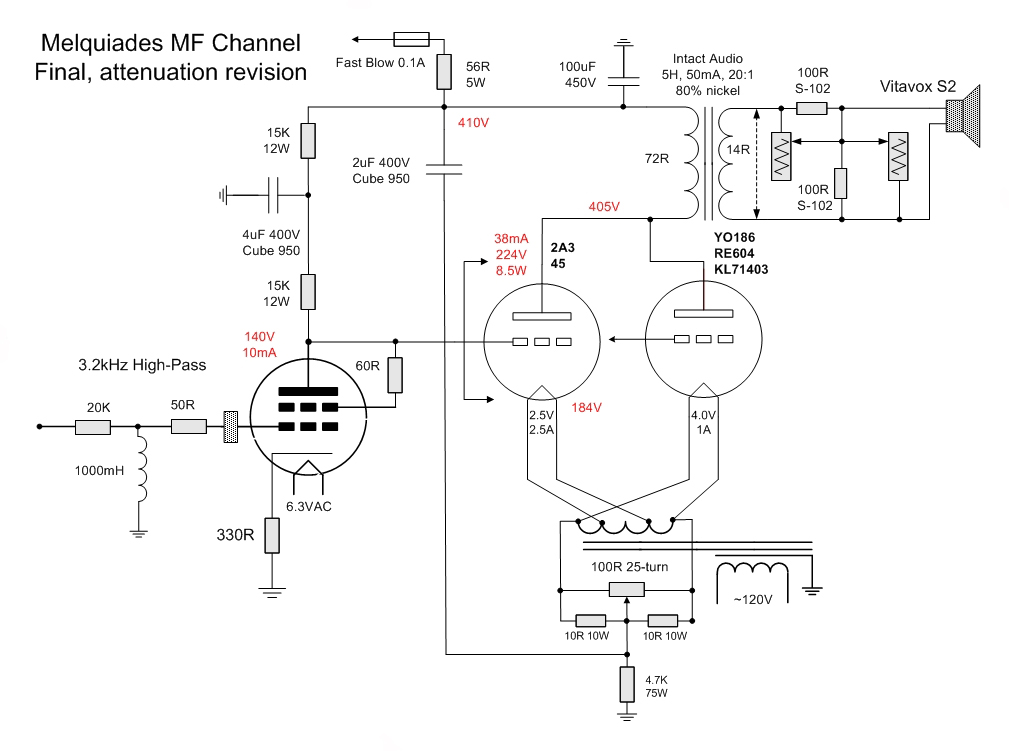
Anyhow, this is the update that I promised. It is what it is. I have updated the circuit of my MF channel where I was trying to depict the logic of my new non-inductive LPAD setting.

Melquiades_YO-186_Attenuation_revision.jpg

Rgs, Romy the Cat


"I wish I could score everything for horns." - Richard Wagner. "Our writing equipment takes part in the forming of our thoughts." - Friedrich Nietzsche
06-26-2009 Post does not mapped to Knowledge Tree
floobydust


currently roaming the US
Posts 62
Joined on 01-19-2009

Post #: 358
Post ID: 10916
Reply to: 10915
The devil is in the details....
fiogf49gjkf0d
 A most interesting post... and I can see how things get altered based on incremental changes to resolve one issue only to find another down the road, which is often disguised by components which simply don't perform in a pure manner. I've not heard any of the 4V tubes you have so I simply have no ability to compare or comment. I do have much experience with the 45 however. I know for certain that all 45 triodes are not equal. Measurements, microphonics and sonics can be quite different based on the internal construction. I don't adhere to brand names for the 45 or 2A3 at this point... I've far too many which are cross-branded to render the branding meaningless. I guess my only real question here is: Have you found differences in internal construction for the YO186 and other tubes as exists with the 45 and 2A3? Also, can you describe which 45 internal constrution your particular 45s are? Perhaps a different one might change the overall (audible) performance.... impossible to know unless you try and compare.

 Dismissing all of the above, it appears you have reached a design which meets your original design goals... well done. I am interested to know if you find any audible changes over time with the DHTs however... especially in contrast to the IDHTs in the rest of the amp.

 Regards, KM


... just because you're paranoid, it doesn't mean they're not after you ...
06-26-2009 Post does not mapped to Knowledge Tree
Romy the Cat


Boston, MA
Posts 10,049
Joined on 05-28-2004

Post #: 359
Post ID: 10923
Reply to: 10916
Constructing Sound
fiogf49gjkf0d
Floobydust, I do not have a lot of experience with listening the 45 of internal construction. I bought a dozen of so 45, all different brands and I will slowly listen them. However, I do not necessarily looking for better tubes but I rather am looking for tube that would comply with my definition of “how it shell be”. Therefore I do not truly look at the construction of the tubes, particularly with DHT, when we have such a differences in construction. Ideals what I would like to have is somebody with you experience in let say 45 tube, to whom I my play my playback and to point out very specifically what in the given sound I would like to change and in what direction. Then you or whoever would be able to point me which brand, which vintage, or which construction I shall use to accomplish this given sonic result. If you wish I might post the picture of the 45 that I have and you might sort them by what you feel is important. Only let me know what to shoot.

I am bit hesitant to use the plug-and-play approach as what I am witnessing not is the proper sonic operation of a new DHT in context of Macondo is a very finicky balance of 3 channels. Do not forget that my MF is not a full–range operation, in full–range it is easy – juts plug-and-play.

The Cat


"I wish I could score everything for horns." - Richard Wagner. "Our writing equipment takes part in the forming of our thoughts." - Friedrich Nietzsche
06-27-2009 Post does not mapped to Knowledge Tree
Romy the Cat


Boston, MA
Posts 10,049
Joined on 05-28-2004

Post #: 360
Post ID: 10928
Reply to: 10923
A new view on the DHT evaluation.
fiogf49gjkf0d

As I said above - the myth of my easy replaceable tubes for my MF channel got evaporated.  Sure, it is physically possible to plug in those 2A3, 45 or 4V tube and they all will work fine but Macondo will not tolerate it. In fact getting now the proper sound from Macondo running MF with YO186 I can clearly see what shall be my next step if I wish to do “it” methodologically appropriate. I need to define what would be this “it”. “It” for me is not the discrimination of tubes but learning to which degree my option for DHT in MF would allow me to mitigate sound. I know that all DHT tube are different but the key is to make my DHT by the means of other Macondo channels, to sound THE SAME (in context of all 6 channels) and they to see what those different DHT will be able to do while they all show off the same sound in context of the Macondo.

So, far I have found the interestingly–proper operation condition only for YO186. I do not mean the operation point for plate but the operation condition in Macondo. Those operational condition imply a very precise balance of

1) MF output volume (.25dB precision)
2) Tweeter output volume (1dB precision)
3) Injection Channel output volume (1dB precision)
4) Fundamental Channel output volume (.25dB precision)

I think the best would be to build up a little chart where I would mark the precise setting for each type of tube that would make it reputable and predictable.

The cAT


"I wish I could score everything for horns." - Richard Wagner. "Our writing equipment takes part in the forming of our thoughts." - Friedrich Nietzsche
Page 18 of 20 (398 items) Select Pages:  « First ... « 16 17 18 19 20 »
   Target    Threads for related reading   Most recent post in related threads   Forum  Replies   Views   Started 
  »  New  DHT driver & input..  Effects of radiation...  Melquiades Amplifier  Forum     25  237802  02-01-2007
  »  New  The one-stage Melquiades...  It's time, what amorphous opt...  Melquiades Amplifier  Forum     74  654914  04-21-2007
  »  New  The single-stage Milq and power Supplies...  Just the tank...  Melquiades Amplifier  Forum     10  95682  05-03-2007
  »  New  The 6E5P tube data...  Bartola Valves: 6e5p beam tetrode SPICE model...  Melquiades Amplifier  Forum     44  463864  07-23-2007
  »  New  6 Channel Version of Super Melquiades..  The first Milq screw up....  Melquiades Amplifier  Forum     131  1202733  08-08-2007
  »  New  My (Amplification + Acoustic System): what is next?..  Macondo and Melquiades in the NEW room....  Audio Discussions  Forum     41  301279  01-10-2008
  »  New  Incorporating active crossovers into DSET..  Thanks...  Melquiades Amplifier  Forum     2  43991  07-22-2008
  »  New  About the life-expectancy of the new production tubes...  Stressing the damn contemporary tubes....  Audio Discussions  Forum     9  89600  12-29-2008
  »  New  Small SET’s bass, besides everything- is it about power..  Importance of OPT and type of tube for SET amp bass per...  Audio Discussions  Forum     4  82722  01-12-2009
  »  New  Macondo: new horizons. A few thoughts in context Zander..  What does make a playback to stop?...  Playback Listening  Forum     9  72238  02-02-2009
  »  New  The period DHT tubes and Swastika..  Maybe there is another solution...  Melquiades Amplifier  Forum     1  27264  04-30-2009
  »  New  Some thoughts about Milq’s MF filter..  High-Pass RL Filter calculator....  Melquiades Amplifier  Forum     2  33396  05-02-2009
  »  New  The DHOFT topology? Do not try it home...  A medley of slow-cooked triodes....  Melquiades Amplifier  Forum     3  46631  05-04-2009
  »  New  Why the tubes shall be the same?..  Not optional anymore?...  Melquiades Amplifier  Forum     7  61912  05-11-2009
  »  New  Valve Technology Timeline..  A good video about tubes making....  Audio Discussions  Forum     5  95304  06-18-2006
  »  New  The DSET perspective examines the Herb Reichert article..  Are you still in Reutlingen, Germany?...  Melquiades Amplifier  Forum     5  93872  07-01-2009
  »  New  About the Critical Audio Tune ™..  “Critical Audio Tune” bay-leave in the soup......  Playback Listening  Forum     5  50593  08-29-2009
  »  New  A full-range quality-triode? Does Size mater?..  A full-range quality-triode? Does Size mater?...  Melquiades Amplifier  Forum     0  16917  12-02-2009
  »  New  About Stupid Dynamic..  Misplaced dynamics....  Playback Listening  Forum     1  20943  08-21-2011
Home Page  |  Last 24Hours  | Search  |  SiteMap  | Questions or Problems | Copyright Note
The content of all messages within the Forums Copyright © by authors of the posts