| Search | Login/Register
   Home » Melquiades Amplifier » R22 (35 posts, 2 pages)
  Print Thread | 1st Post |  
Page 2 of 2 (35 items) Select Pages:  « 1 2
01-03-2022 Post does not mapped to Knowledge Tree
Domidaw
Posts 15
Joined on 08-09-2021

Post #: 21
Post ID: 26656
Reply to: 26655
Transformers
Tr2 is 100Va Tr3 is 120Va. 508v is at the output of the transformer connected to the load. I also measured tube heaters. The 6c33c is 14.2v and the 6e5p is 8.6v. I will not hide that I spent some time staring at the glowing tubes, with only the heating connected. Well, it's been quite a long time.  I just never saw a glowing 6c33c so I was looking at it like a very little child, looking at a glowing Christmas tree for the first time. Is it possible that with over 14v on tube it got damaged and hence my troubles are from this? I have 14 more 6c33c, but they are at my brother's house. Today I will go to him and bring them to my apartment.
01-03-2022 Post does not mapped to Knowledge Tree
anthony
Posts 338
Joined on 08-18-2014

Post #: 22
Post ID: 26657
Reply to: 26656
Primaries
Those both look fine, but all your voltages are hot...all of them.  From afar it seems as though the primaries are not correct for the mains supply by about 15% eg. wound for 200V primary but you have 230V, or something like that.  Where I am has nominal 230V mains but the house always has 240V so I have all my power transformers wound to suit what I actually have which is 240V.  This is not necessary related to the problem you are having, but that 6e5p filament is running 35% above spec. and the 6c33c 13% which I would definitely bring down.  
01-03-2022 Post does not mapped to Knowledge Tree
Domidaw
Posts 15
Joined on 08-09-2021

Post #: 23
Post ID: 26658
Reply to: 26657
Voltage across the 1-ohm R21
Is 88mV. I also noticed that resistor R2 is also very hot ... Can bridge rectifiers have any influence on all of this?
01-03-2022 Post does not mapped to Knowledge Tree
anthony
Posts 338
Joined on 08-18-2014

Post #: 24
Post ID: 26659
Reply to: 26658
R2
R2 gets hot.  I think I mentioned earlier that it will also be hot...it is dropping 250V and running 17ma which is a bit over 4watt.  From memory, that tube should be biased to about 35mA.

Bridge recitifiers will only really matter here if you are using active rectifiers which will need an additional cap at their output, otherwise if using standard schottky's then I doubt there will be a problem unless they are under-rated (should be at least 2.5 x the secondary voltage).
01-03-2022 Post does not mapped to Knowledge Tree
JJ Triode
Posts 99
Joined on 09-12-2007

Post #: 25
Post ID: 26660
Reply to: 26658
Factor of ten?
Are you sure you don't mean 880mV or equivalently 0.88V ? If it is 880 mV then the output tube plate current is indeed 880 mA, which is way too high, but at least then we know C10 is definitely not the problem. What is the voltage at pin 5, the output tube grid? Per the schematic it should be about 100V below ground. If the current through R22 and V4 is only 88 mA then I have no idea what's going on.
01-03-2022 Post does not mapped to Knowledge Tree
deemon
Posts 24
Joined on 05-25-2004

Post #: 26
Post ID: 26661
Reply to: 26656
Tube current measurement
Hi Domidaw ! 
The first thing that we need to find out - is a REAL tube plate current at the moment when the R22 resistor starts smoking . I mean not a calculations that might be based on some faulty conclusions but a real current that an ammeter does show . What you need to do is to disconnect wires at the D testpoint ( tube plate ) and connect any reliable ammeter between them ( maybe a multimeter in "ampere" mode ) , turn the amplifier on and then tell us what current multimeter shows . All further actions will depend on a result of this measurement , of course ....
01-03-2022 Post does not mapped to Knowledge Tree
Romy the Cat


Boston, MA
Posts 10,166
Joined on 05-28-2004

Post #: 27
Post ID: 26662
Reply to: 26661
Thanksm Dima
Domidaw, I am not participating in helping you too much because I have my own diabolical fun observing your suffering. Sorry, my friend, I was in the same shoes so many times, literally having the same feeling and speaking with the same language, that observing you I feel like I am reading my own diary . Deemon above is Dima, the gentleman without whom the Milq would never materialize. You are in very good hands. You know, my valve who gave to people chemotherapy say to them that it doesn't work if it would not hurt 😊


"I wish I could score everything for horns." - Richard Wagner. "Our writing equipment takes part in the forming of our thoughts." - Friedrich Nietzsche
01-04-2022 Post does not mapped to Knowledge Tree
Domidaw
Posts 15
Joined on 08-09-2021

Post #: 28
Post ID: 26663
Reply to: 26662
Data and photo with a view of the battlefield
Hello Dima !!!! At point D I have 0.920 mA ... at 198v on pin 4. 238v before resistor R22 and 200v after resistor R22. On pin 5 I have -82. There is 82mV across the R21 resistor. I noticed that when I turn the VR2 potentiometer, thus increasing the reading along the R21 resistor, the voltage behind the R22 resistor decreases, the voltage in front of it, i.e. 238v, does not change.
Ps. Romy, I think you might have mistaken my thanks to you. I thank you for contacting Dima regarding my case. There was nothing sarcastic about it. It's all just love. You know how I am suffering now, because there is no better word than suffering to describe the situation I am in now, so you also realize how much help of all of you mean to me.  20220104_120330.jpg
01-04-2022 Post does not mapped to Knowledge Tree
Domidaw
Posts 15
Joined on 08-09-2021

Post #: 29
Post ID: 26664
Reply to: 26663
My "Bro science"

5hours pass when I sit in the chair and stare at work of my life (amplifier), like some haunted man. As you can see, I divided the amplifier into two parts, the power supply is  in a separate housing. I did it because the chokes and the OTP transformer were delivered to me, in large cans flooded with resin. I just couldn't find an idea how to put it all into one, not too large housing. So I decided to do the same as Romy did with his big 6-channel amplifier, that is, to divide it into two parts the power part and the amplifier part. As a result, I gain a small space occupied by the entire amplifier. But now I wonder if this is not  the cause of my problems. I checked all connections again and I am not able to find the error, so I think that either one of the components is damaged or I made some technical error that is the results from my ignorance in the field of electronics. I am reading such an article now: https://phys.libretexts.org/Bookshelves/University_Physics/Book%3A_Introductory_Physics_-_Building_Models_to_Describe_Our_World_(Martin_Neary_Rinaldo_and_Woodman)/22%3A_Source_of_Magnetic_Field/22.02%3A_Force_between_two_current-carrying_wires  and I wonder if my problem is not some interference betwen wires in the cable that connects Ps with  a amplifier part.
01-04-2022 Post does not mapped to Knowledge Tree
JJ Triode
Posts 99
Joined on 09-12-2007

Post #: 30
Post ID: 26667
Reply to: 26663
Three different currents that should all be the same
Hi again Domidaw. Your latest results look inconsistent: a 38V drop across 50-ohm R22 would imply 0.76A or 760 mA flowing through R22. If C10 is not leaking any significant DC current then this 760 mA should be the current through R21 and point D. But you have 82 mV across the 1-ohm R21, implying 82 mA of current. Then at D you say it is only 0.920 mA! Something is wrong; perhaps the resistances are not what you think? Also, to measure a current you have to open the circuit at the desired point and make all the current flow into one lead of the meter and out the other; it is not like measuring the voltage to ground. How did you measure the current at D?
01-04-2022 Post does not mapped to Knowledge Tree
Domidaw
Posts 15
Joined on 08-09-2021

Post #: 31
Post ID: 26668
Reply to: 26667
The current at point D
I made this measurement in such a way that I unsoldered the wire from pin 4 (black in the photo) and connected to it the red clip from the multimeter, and to pin 4 I connected the black clip from the multimeter. I set the multimeter to the mA reading position. Is it possible that I somehow burned the output transformer and this is the problem ? I have to try the other one.
01-04-2022 Post does not mapped to Knowledge Tree
Domidaw
Posts 15
Joined on 08-09-2021

Post #: 32
Post ID: 26669
Reply to: 26668
New multimeter
I ordered new  wires and ordered a new multimeter. Maybe mine is faulty. This is Chinese, not very expensive equipment. I will replace all the wires in amplifier  and measure everything again with a new multimeter. Fu.ck....
01-10-2022 Post does not mapped to Knowledge Tree
Domidaw
Posts 15
Joined on 08-09-2021

Post #: 33
Post ID: 26670
Reply to: 26669
News from the war zone
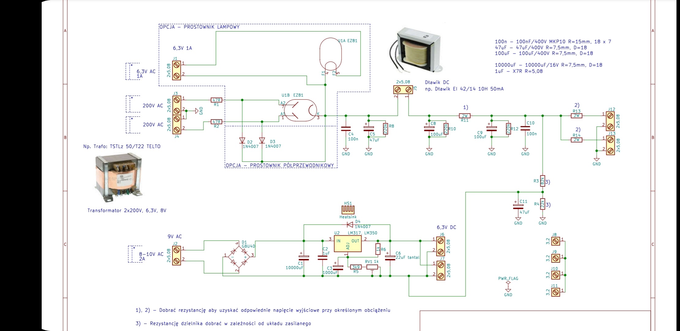
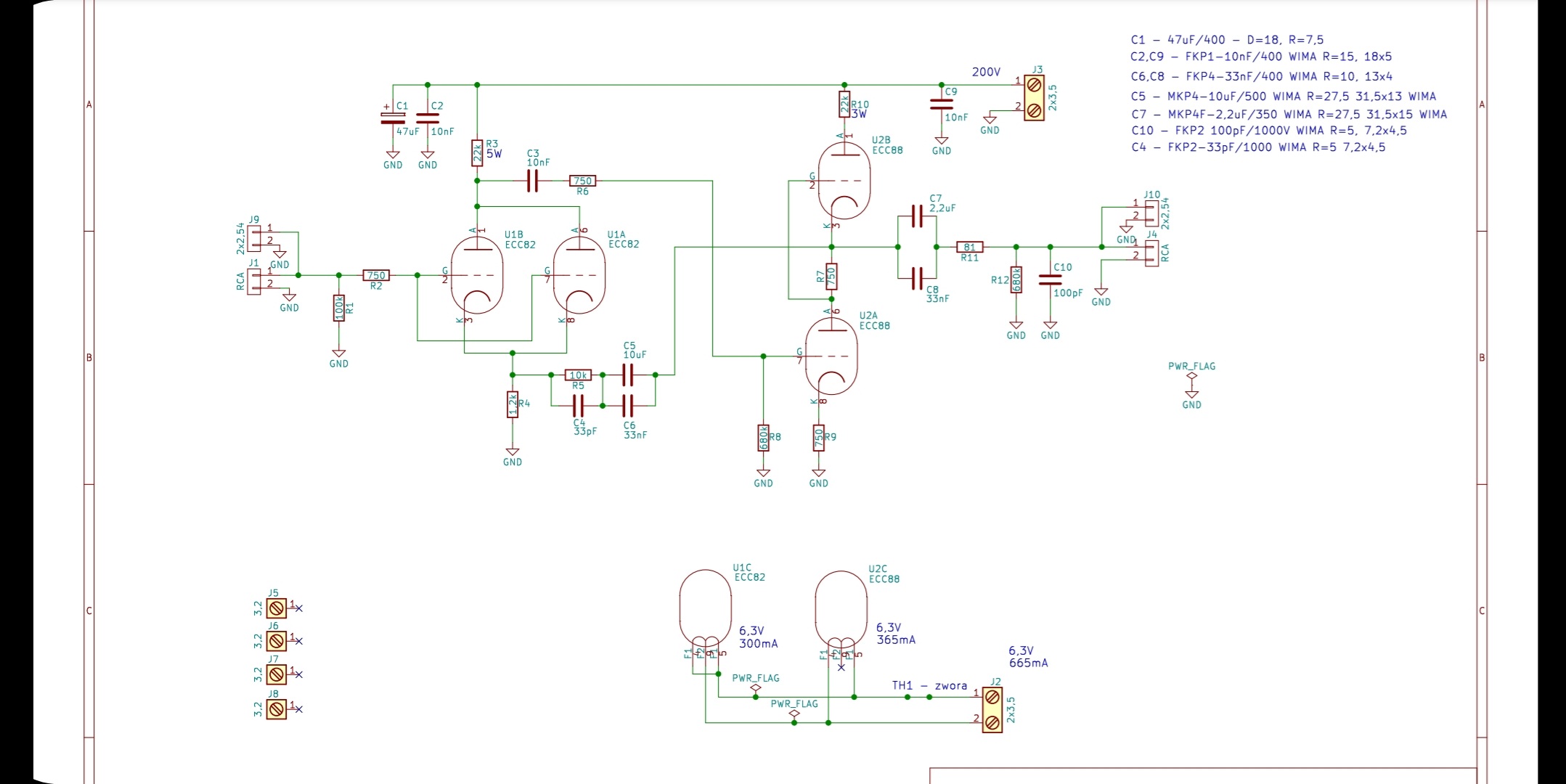
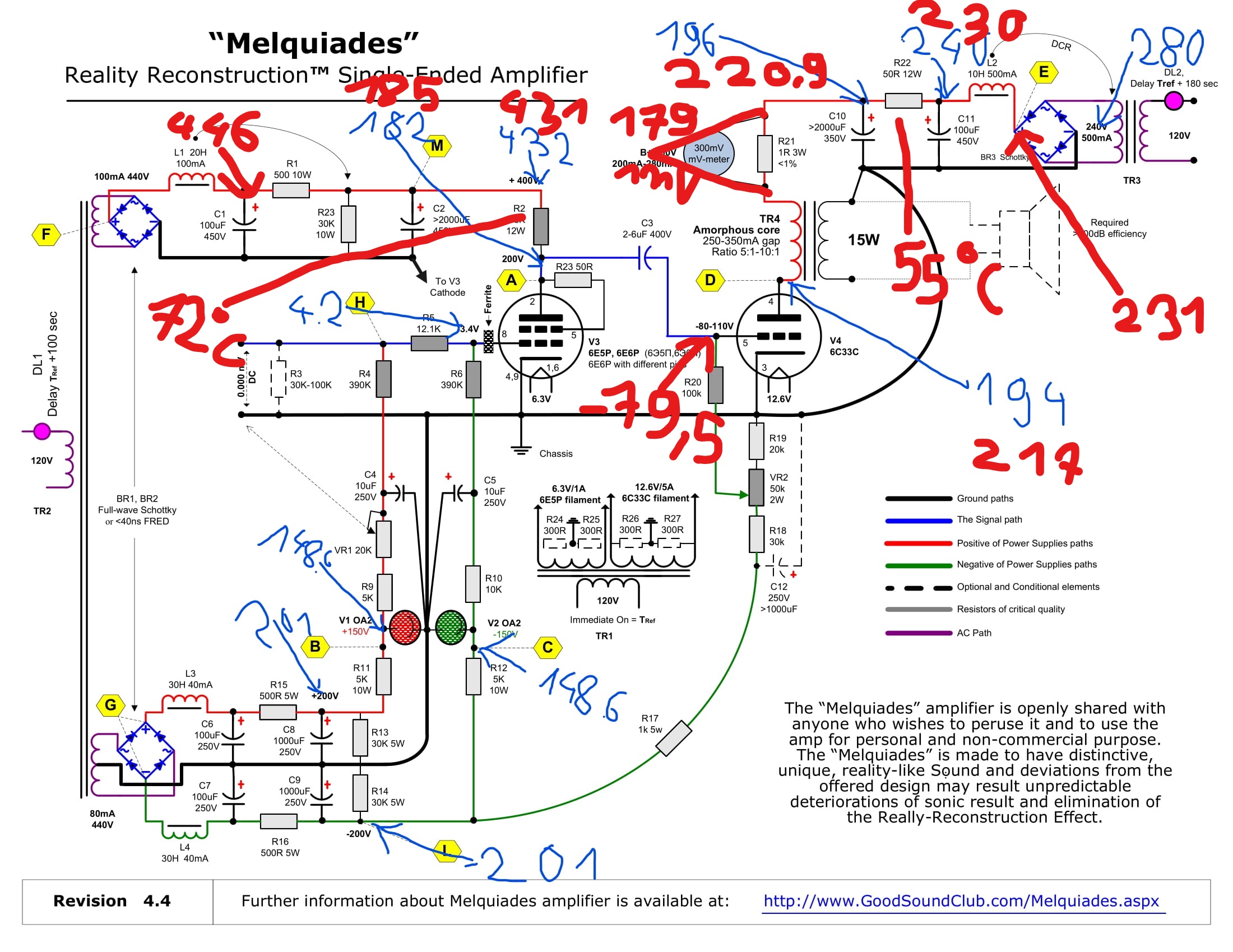
I replaced all the wires, replaced the capacitor C11, C10, returned to the 12w resistor R22, also replaced the L2 choke. Now I sit for over two hours next to amplifier, just like sitting at the bedside of a sick loved one person.  Nothing is burning and it does not heat up much. I put a thermometer from a multimeter on the resistors that were the warmest. After two hours of continuous operation, the R22 resistor has a temperature of 55 degrees Celsius, and the resistor R2 is 72 degrees Celsius. The voltage across R21 drifts between 179mV and 181mV. Please look at the diagram, the red numbers are the actual measurements ..... I am mentally and physically exhausted (my back hurts enormously) when I waited for a new multimeter and cables, at that time I assembled the preamplifier (diagram below). It was on PCBs so it was easy, but it still took some concentration and some work. So I didn't leave this crazy mental  state for even a day. I look forward to your evaluation of my new measurements ... sInkedMelquiades_SET domidaw.jpg
Screenshot_20220110-180229_Drive.jpg
Screenshot_20220110-180251_Drive.jpg
01-10-2022 Post does not mapped to Knowledge Tree
JJ Triode
Posts 99
Joined on 09-12-2007

Post #: 34
Post ID: 26671
Reply to: 26670
Ready to connect a speaker!
Hi Domidaw, it looks like your amplifier is working pretty much correctly. The plate current in the output tube is a little below the recommended range (180 mA versus 200-280 mA in Romy's diagram) but too low is better than too high and you can adjust it by changing VR2 (monitor voltage at R21 to get into the desired range.) I have no idea what was wrong before.

I can't say anything about your preamp as I am not familiar with the design. The only strange thing is that I don't see a volume control anywhere, but maybe I missed something.  Anyway now that you have one working channel, you can connect a speaker to the amplifier, feed in some music and check that you have something recognizable coming out.  By the way if you don't have a speaker connected then you should have a "dummy load" (a power resistor of about 8R) across the output terminal of the amplifier.
01-10-2022 Post does not mapped to Knowledge Tree
Domidaw
Posts 15
Joined on 08-09-2021

Post #: 35
Post ID: 26672
Reply to: 26671
Thank you JJ.
I connected the loudspeaker to check if the music was flowing from it. The amplifier works !!! I hear the music!!! I'm exhausted. Now it's evening at my place, I can hear the rain outside. I think I'm going to do what I wanted to do countless times while building this amplifier ... I'll will just turn off the lights, go to the corner of the room, sit on the floor there, curl up into a ball and cry loud and hysterical. Or no..., I will just choke this hysterical loud cry until it is barely audible and I will cry like that. Like  a real man is crying.
Page 2 of 2 (35 items) Select Pages:  « 1 2
Home Page  |  Last 24Hours  | Search  |  SiteMap  | Questions or Problems | Copyright Note
The content of all messages within the Forums Copyright © by authors of the posts