|
Posted by Domidaw on
12-29-2021
|
Romy,
I know you are busy building new speakers at the moment, but I have to ask for your help.
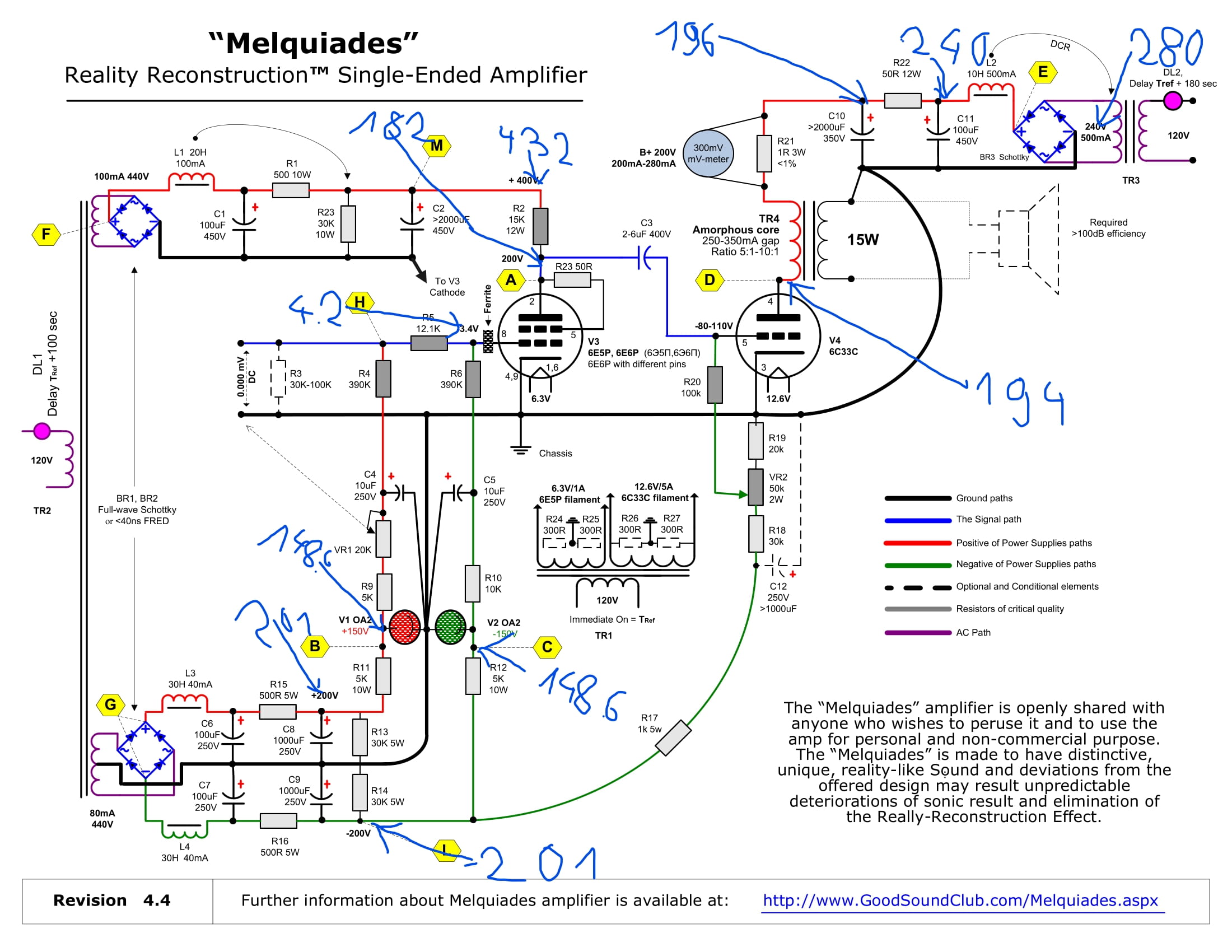
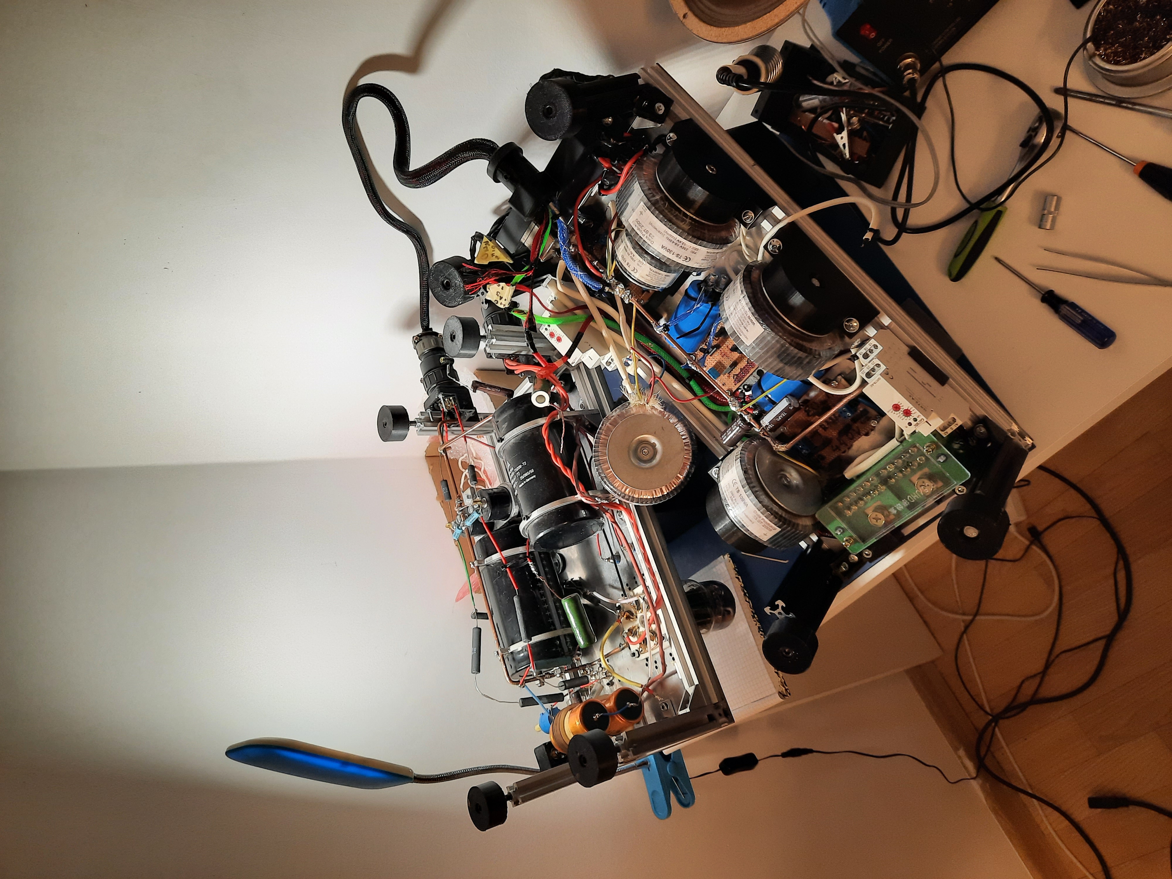
I started putting together the full range melquiades amplifier. This is my first time building any electronic device, my knowledge in this subject is very small. Currently, I have almost one channel ready. I writes "almost" because I have one problem, namely the r22 resistor from the scheme, heats up very much and then starts to burn. Otherwise everything looks fine, all the voltages from the scheme are rhe same. All parts have the same values as in the schem, the diodes are cree 303060, I live in Poland, so the primary winding is for European voltage.
I have no idea why this resistor goes out, what could I do to fix this situation?
Best Regards
D
|
|
|
|
Posted by anthony on
12-29-2021
|
R22 is there to drop the B+ to the correct level and needs to be rated so it can dissipate quite a bit of power i.e. heat. It is 12 watt in the schematic but maybe the one you are using is rated lower or perhaps you have a higher secondary voltage on the power transformer TR3. If you are using higher than 50ohm for R22 then you will probably also need to use a higher wattage resistor.
If this resistor is under-rated, others to look at include R11-R16, R23, R2 and perhaps R17 if you needed to install it.
Good to hear this amp is still being built by people...it is a good one when paired with appropriate speakers.
|
|
|
|
Posted by Domidaw on
12-30-2021
|
Anthony,
First of all, I would like to congratulate you on making your amplifier. I have been following your build from the beginning and now that I am building my own amp, I appreciate your work even more. I admire your plan and execution of the amplifier.
Coming back to the topic (this topic should probably be moved to the question and answer thread) My TR3 is a toroidal transformer that was made for me after presenting the diagram for the contractor. The label says sec. 240v but when I connect a "bare" transformer to the mains and measure it, it shows 280v. I changed the r22 resistor to 20w and the problem does not disappear. It heats up suddenly, after 30 seconds I can't even touch it, and after 2 minutes it starts to swell. Something is not as it should be. I checked the connections a million times and it looks like everything is connected according to the scheme ....
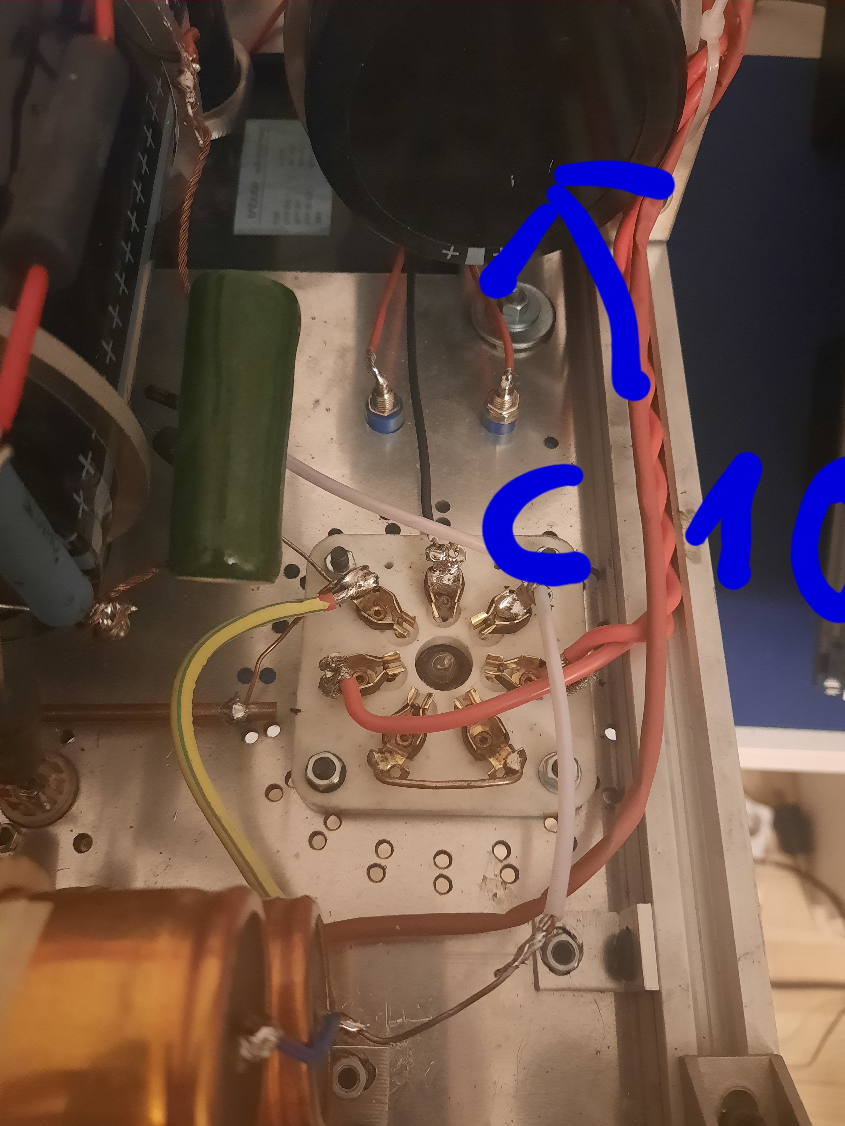
As you can see in the attached photo, I have 240v in front of the resistor, and behind the resistor I have as much as in point D. And this voltage can be regulated via the VR2 potentiometer. I have no idea what to do next.

|
|
|
|
Posted by anthony on
12-30-2021
|
I am sure I made a reply last night, but it is nowhere, so here it is again.
44V across R22 is equivalent to 0.88A which is way too high and would require a resistor rated better than 40W. R2 is dropping more voltage than it should. I would look at the datasheets for 6c33c (in particular) and 6e5p to be sure that the sockets are wired correctly. For example that the B+ in question is wired to pin 4 and the not pin 5 (pin 4/anode is the big hole in a 6c33c socket). The datasheets will mention whether they look from bottom-up or top-down (not all diagrams are the same) which if not noticed will make the pins incorrectly identified.
|
|
|
|
Posted by Romy the Cat on
12-30-2021
|
I wish it would be true and I would be busy to build my loudspeakers. Unfortunately it is a lot of work and I did not have even time to look at my site. The r22, the power resistor is not necessary the one which mitigate voltage in your tube. Certainly it might but it is not good idea to adjust voltage to transferring it into heat. The main objective of r22 is to decouple one stage of filtration from another. The input LC filter does what it does and the capacitor across as a second filtration stage decoupled by a resistor. If it gets overheat then you drive too high current over it. You drive too much current only if the impedance of your load is too low or if your supply voltage too high. I would not give up the power rating of that resistor but I would rather recommend to find the reason what make current over it too high
|
|
|
|
Posted by Domidaw on
12-31-2021
|
I mentioned earlier that this is my first electtrical device that I build. Realizing that it could be dangerous to my health and even my life ... I planned and soldered all the parts for a couple of months. I know every connection and every component value by heart. This scheme was written into my DNA ... So Anthony, there's no way I made a connection error somewhere.
My plan is this, I have ordered 100w resistors just in case, but I'm going to unwind the secondary on the transformer to get it equal to 240v, And then I'll see what happens

|
|
|
|
Posted by Romy the Cat on
12-31-2021
|
Domidaw, I am not sure if I will be wrong if I say that this amp was first electrical device I build also. so I went over the same problem as you are going. trust me I made a number of ridiculous mistakes as well and so many times I call to people to help me to find a bug, it was mostly Dima. What Dima tough me was to from a point when I know what voltage is correct for each step and each part and measure it before and after. sooner or later, I was able to find the problem. I would insist that the circuitry is correct, it was followed by multiple people. it is most likely (above I called it lost in the translation) you made some kind of wrong decision converting the circuitry to 220 volts. Look at the voltage and the secondary of your power transformer and go step by step from there. The secondary of your transformer supposed to have 240V not 280V this is obvious.
So, let presume that you have a wrong transformer, so how to fix it. You can beef up the resistor and to burn excessive voltage there. if so, do not complain that the resistor is getting hot but it is a bit wasteful way to do the things. Also, the biggest problem is that you are driving your input choke at much higher current, way above critical current. I am not sure that your input will work properly in this scenario, so to make things work properly you need to put a resistor to burn before the choke. It will have its own problem as your rectification want to “see” the input choke not a resistor. You certainly can make it work electrically but you need to evaluate how it impacts sound. what is at the schematic is very play calculated in poop chart filter with a minimum current in place end this configuration was tested electrically and sonically. introducing another idle burning resistor will give another variable and I did not investigate it, so I cannot comment upon its Sonic consequences. so, where up to me I would just change the transformer to be on a spot. if you do not want to do it because we have one centralized transformer for entire amplifier then I would just order one extra B plus transformer with correct output voltage. If, as you finish the amplifier you like the sound then it would be withy to order another centralized transformer.
|
|
|
|
Posted by JJ Triode on
01-01-2022
|
I haven't tried to build a Melquiades but I understand tube electronics decently, so I'd like to comment on this problem.
The main question is why Domidaw's output tube is apparently carrying 3 to 4 times as much plate current as it should be. It is possible the tube is not being biased correctly, or is just a far-out-of-specification tube, but if it is carrying that much current (880 mA) then the tube should be overheating, showing red plates or just a ridiculous amount of heat coming off the tube. Even if the tube is internally shorted from plate to cathode, given the assumed current and measured plate voltage, the tube should be running perceptibly too hot.
If the tube is not running excessively hot then maybe it isn't really carrying all the current running through R22. Maybe C10 is shorted to ground and is carrying most of the current passing through R22. Domidaw should measure the voltage across the 1-ohm R21 to determine the current going to the output tube. If it is 0.88V then C10 is not shorted and the tube is really drawing excess current; if it is about 0.2V then the tube is drawing about 200 mA as it should, and C10 is shorting. If C10 is OK then a next thing to try would be replacing the output tube with another, preferably good-tested 6C33C.
I don't think the difference between 240V and 280V at the power transformer secondary could be the cause of such a large anomaly, and the transformer should not be tampered with until more is known about where all that current is going. Good luck,
JJ
|
|
|
|
Posted by Romy the Cat on
01-01-2022
|
|
JJ, I was under impressions and hia plate current is fine, so I would not blame the output tube. Pay attention he has 196 volt voltage, which is perfectly fine. Since he has one channel working in another not then it would be easier to go steps by step and compare right and left channels.
|
|
|
|
Posted by JJ Triode on
01-02-2022
|
Domidaw seems to be saying he has only one channel almost working, this one with the burning resistor. I don't think he said he has one (other) channel working correctly. If he is really dropping 240 - 196 = 44V across 50 ohms, then he has 44/50 = 0.88A flowing through R22, as Anthony said. If some of this DC current is not shorting through C10 to ground as I suspected, then it all has to flow through R21, TR4 and V4 in series; there is nowhere else for it to go. This would gives a plate current of 880 mA through V4, resulting in 170 watts plate dissipation given the plate voltage of 194V. The rated maximum dissipation for that tube (both plates in use) is 90 W. According to the schematic the dissipation in V4 should be 40-56 watts. I see only three possibilities:
1. Domidaw is mistaken about the resistance of R22, the voltage across it or both, such that the current is not close to 0.88A (but then why is it burning?)
2. Some DC current is shorting through C10 to ground, hence C10 is defective and should be replaced.
3. The tube is really carrying 0.88A current, indicating the tube is defective or wired wrong, or maybe there is a strand of wire or solder or something shorting the socket.
The current through R2 has to go somewhere, and it can only go through C10 or eventually V4. It can't just disappear.
|
|
|
|
Posted by Domidaw on
01-02-2022
|
Because I feel that with your help, sooner or later I will solve this problem. So far I have been feeling very frustrated for days, so I decided to post this on the forum as a last resort. I do not know any people who know electronics construction. If I knew a person whom I could call with my problem then .... well, that person would probably change his number because I would have massacred him with my phone calls.
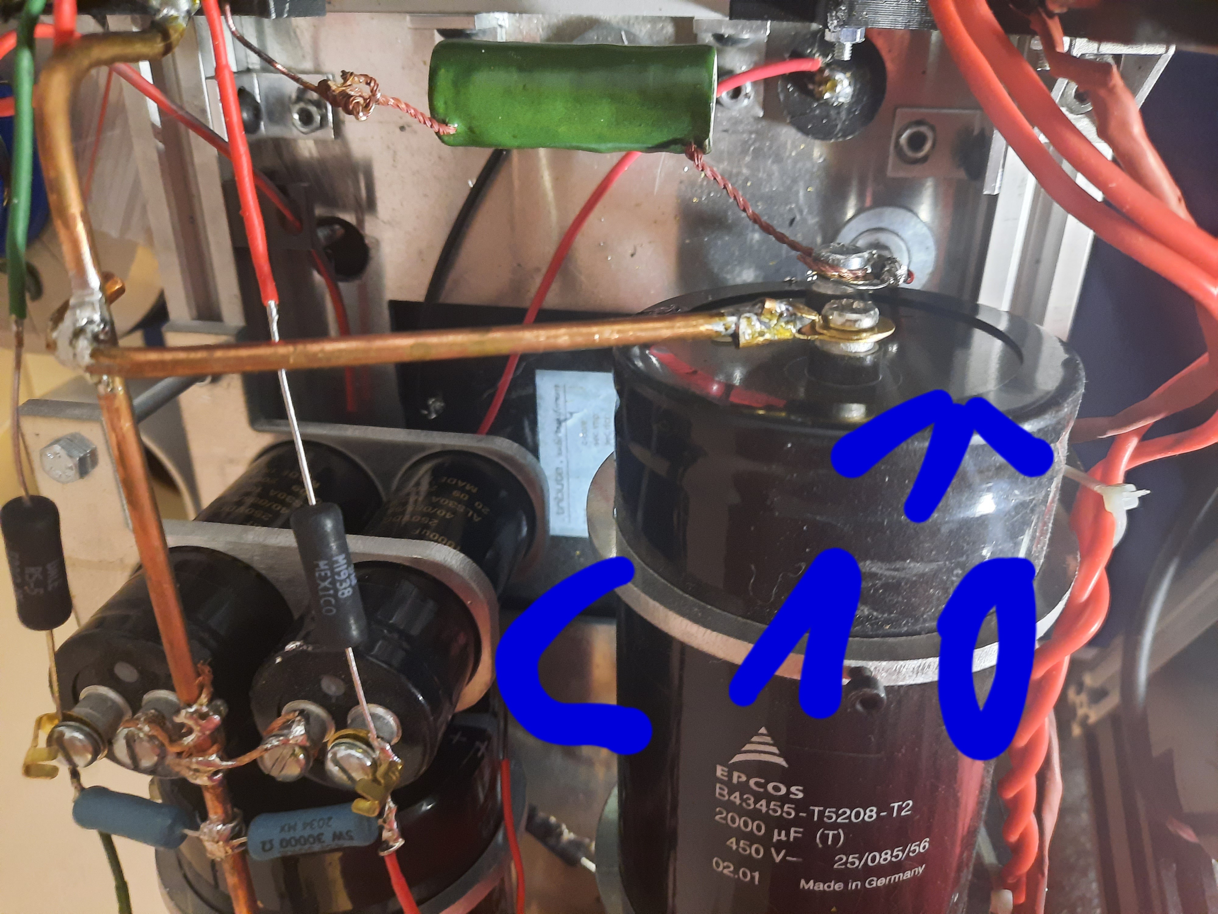
I'm not home until Wednesday, so there's not much I can do now. I am going to order a new transformer tomorrow. Before leaving, I checked the capacitance of the capacitors with a multimeter and they all seams ok, so they are rather functional. The photo shows the capacitor c10. Its minus is connected to ground, its plus goes to the output transformer, which is directly below it. From the transformer, the black wire goes straight to pin 4 in the socket 6c33c. The r22 resistor is a 50ohm 12w ommit, but I replaced it with this big 50ohm 20w green resistor because I could get it quickly locally.
I would like to add that I did not start building a second monoblock ...


|
|
|
|
Posted by JJ Triode on
01-02-2022
|
Domidaw, you wrote:
The photo shows the capacitor c10. Its minus is connected to ground, its plus goes to the output transformer,
According to the schematic it is the grounded (minus) end of C10 that should connect to one side of the output transformer's secondary winding. The purpose of this connection is simply to establish a ground reference for the speaker circuit. This side of the output secondary should also connect to one speaker terminal, probably the black one; the other side of the output secondary should connect only to the red output terminal, nothing else. The output transformer primary winding is of course in series with the output tube plate.
The plus end of C10 should connect to R22 and to the output transformer primary winding (perhaps this is what you meant) with the other end of the output primary going to the output tube plate. However, between the plus end of C10 and the output primary you should have that small resistor R21 whose voltage drop enables you to calculate the true current through the output tube. I urge you to measure this while the amplifier is running, to see where the current is going.
Maybe I am misunderstanding how that capacitor is supposed to be connected, but in your photo I see plus signs "+" on the opposite end from where you have R22 connected. Anyway, other tests you might do include the following:
1. With the amplifier turned off and all capacitors drained of energy, measure the DC resistance (after all transients go down) from the connection point of R22 and C10 to ground. It should be nearly infinite, but I still suspect a short here.
2. With the output tube out of the socket, measure the DC resistance from the tube's plate to cathode, to make sure is in not shorted internally.
3. With the amplifier off and all capacitors drained, and the output tube out of the socket, measure the DC resistance between the socket cathode and plate pins, to make sure there is no short at the socket or through its connections to other parts.
I emphasize again that there has to be some path to ground for the excess current through R22 when the amplifier is on, and that path needs to be identified. There is no way a 20% excess voltage at the power supply should be causing a 300% excess current through the output tube.
|
|
|
|
Posted by JJ Triode on
01-02-2022
|
|
If C10 is connected backwards there could well be a large leakage current through it. It may also have been damaged if this is the case, requiring its replacement.
|
|
|
|
Posted by Domidaw on
01-03-2022
|
|
Or whatever you call it, it says there is no sucha option that I make a connection error, but hey..., I'm 41 years old and I know from experience that sometimes this voice is wrong ...
As I mentioned, I am not in the apartment at the moment, but I can see these connections rigt now in front of my eyes ... On the output transformer I have Ls-, Ls +, b +, and anode markings, so ls + is connected to the red speaker socket, Ls- is connected to the ground bus and to black speaker socket, the minus from the c10 capacitor is connected to the ground bus. resistor r22 is connected to plus on c10, resistor R21 is also connected in the same place, then the connection goes from R21 to the tap on the output transpormator marked as B +, then from the tap marked as anode, the connection goes to pin 4 in the 6c33c socket. If you look at the photo posted by me, above the 6c33c socket you will see two small blue sockets with two red wires coming off. These wires are connected to both sides of the resistor R21. These are the sockets where I can insert the probes from the multimeter for reading mV.
Honestly speaking, today I haven't slept all night (This is not a metaphor by any means) thinking about it all, so now is morning and I'm fucked up. I decided to stop my little vacation and go home, lock myself in there and not go out until this amp starts working ....
|
|
|
|
Posted by Romy the Cat on
01-03-2022
|
Domidaw, it's kind of laughable at what you are feeling now it was absolutely exactly what I was feeling for a few months of building Milq. I know exactly how you feel. I called to Jima and ask him to help you, he most likely will post for you instructions later on.
|
|
|
|
Posted by Domidaw on
01-03-2022
|
And The first thing I did was I grabbed the multimeter and started measuring what JJ suggested. I think we're on the trail of "something". I discharged all the capacitors in the amplifier and with the amplifier turned off, when I put the red tip of the meter to the point where plus C10 and R22 meet, and the other, black end to ground, I did not see infinity, only 2ohm, then slowly but steadily this value increases. ... and when at 22ohm I disconnected the multimeter probes and moved the red to pin 4 and the black to pin 3, these 22ohm appeared to me and again slowly but very steadily this value goes up .... And the same thing happened after removing 6c33c .
On this moment I have to stop my acting as Sherlock Holms and I have to sleep for two hours. That night, resistors, capacitors, wires and all the rest of it was shooting at my mind like AK47. I'm exhausted. I prefer to be focused when I connect the amplifier to AC, the world certainly does not need me, but my children certainly are...
Ps.Thanks for help Romy
|
|
|
|
Posted by JJ Triode on
01-03-2022
|
Domidaw, you are looking at the right things but there is something to consider: when you put a resistance meter across a discharged capacitor you see a low resistance initially because the battery in the meter is charging the capacitor a little, so current is flowing. The measured resistance will rise until it approaches a constant value, so you need to wait until the resistance stops changing. If C10 is OK and connected correctly, the resistance should stabilize at a very high value, I would guess in the mega-ohm range. If my theory is correct that the excess current of about .68A is leaking through C10, you will see a steady resistance of a few hundred ohms. The measurement at the tube socket is essentially the same because the DC resistance of the output transformer primary and R21 are small.
Please review the polarity of C10 carefully. On the side of C10 toward the camera in your photo there is a "+" at the bottom. At the top you have the terminal toward the camera connected to ground. Could this be backwards?
Good luck and by the way Happy New Year to all, JJ
|
|
|
|
Posted by Domidaw on
01-03-2022
|
|
And this capacitor is connected as shown in the photo. its minus goes to mass, its plus goes via R21 to the B + tap in the OTP transformer. I waited for the resistance to stabilize, which started at 2 million ohms and stopped at 42 million ohms . I also checked the voltage of the TR2 transformer and although the marking says 440v, it really has 508v!?!?
|
|
|
|
Posted by anthony on
01-03-2022
|
 Domidaw wrote: Domidaw wrote: | | I also checked the voltage of the TR2 transformer and although the marking says 440v, it really has 508v!?!?
|
|
Domidaw, when you read 508V for TR2, was the transformer in the circuit with a load applied or was it out of the circuit by itself? Power transformers will give high secondary readings without a load applied but when the expected load is used they should reduce to the specified voltage. One of the signs of a good transformer is little difference in secondary voltage between unloaded and loaded.
But if that is 508V reading in-circuit then there is 60-70V too much there too. What current are the power transformers rated for, or how many VA? Maybe TR2 and TR3 are designed for much higher loads which is why when used in Melq we are seeing over-voltage. I would also check the voltage of the secondary feeding the bias circuit.
Btw, I commiserate the feelings you are having right now...I've been there...but it sure does feel good when the problem is found.
|
|
|
|
Posted by JJ Triode on
01-03-2022
|
|
It sounds as though C10 is OK and correctly connected. C2 is OK as well considering it is in parallel with a 30k resistor. The next thing I think, is to turn on the amplifier with both tubes in place and check the current through R21. If R21 and hence the output tube are really carrying 880mA then the tube is defective or not biased properly. Maybe try adjusting VR2 to bring the plate current down to 280 mA, also checking the (negative) grid bias voltage. Beyond this I am really running out of ideas of what might be wrong or how to diagnose it.
|
|