Rerurn to Romy the Cat's Site
In the Forum: Horn-Loaded Speakers
In the Thread: Jessie Dazzle Project
Post Subject: Adjustable rear chamber (Photos)Posted by jessie.dazzle on: 7/16/2008
Ronnie wrote (and posted the following image):
"...I was thinking the same. But perhaps rubber rings can be used to seal the back chamber to make it instantly tune-able (without the hard foam)..."
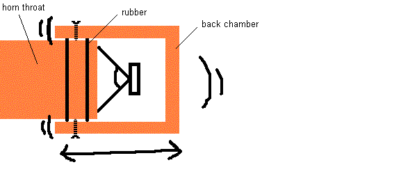
Romy wrote a thread called the "Practical Guide to Back Chamber Tuning", complete with illustrations.
http://www.goodsoundclub.com/Forums/ShowPost.aspx?postID=6011#6011
First thank you Ronnie and Romy...
I took your thoughts into the workshop (which is also the living room), and here is the result :
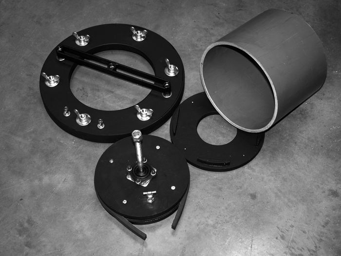
Above: The parts for one rear chamber. Rather than sliding a cylinder on the outside of the horn as in Ronnie's illustration, I decided to sleeve the horn's inner surface, and fabricate a piston that would slide within that sleeve. The cylinder is a heavy duty sewer pipe (expensive, and I had to buy 3m) The piston (foreground) has a rubber seal, which I've pulled out of its groove for the photo. The mechanism that drives the piston is a threaded shaft, with one end welded to a mini turn-table, and the other end destined to be threaded into the support that runs across the large circular clamping ring in the upper left of the image. The disc in front of the cylinder is the "other end" of the chamber; this is where the driver is bolted.
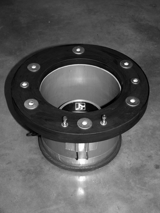
Above: Driver installed (Fane Studio 8Ms in this case) and wired to the binding posts visible on the clamping ring. The cylinder as well as the holes where the wires come through are sealed with silicone.
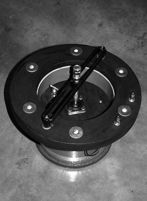
Above: Piston installed. Note the little valve in the piston... The air-tight seal works better than expected, so I decided to put a in bleeder, which, if opened, will keep from sucking or blowing a hole in the drivers membrane while adjusting the piston.
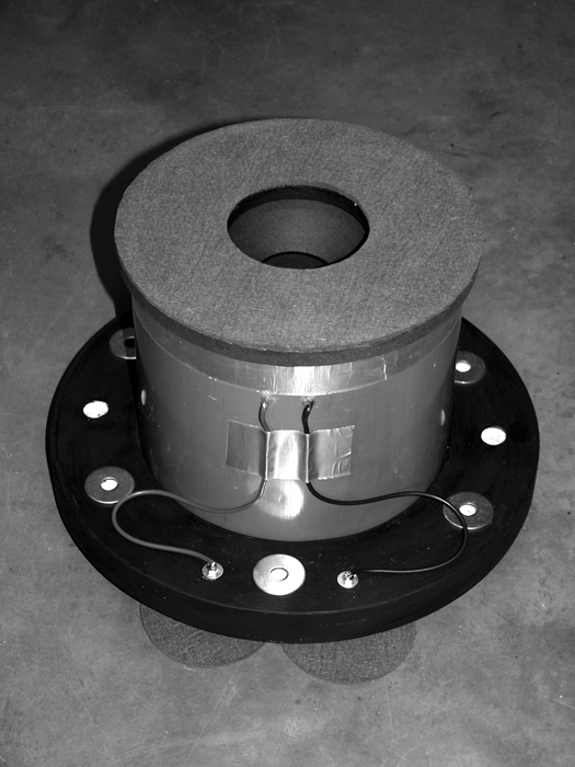
Above : Assembly ready to plug into the horn. The face that mates with the horn (top of image) is covered in wool felt (the two little felt discs under the clamping ring are there to protect the binding posts while taking the photo).
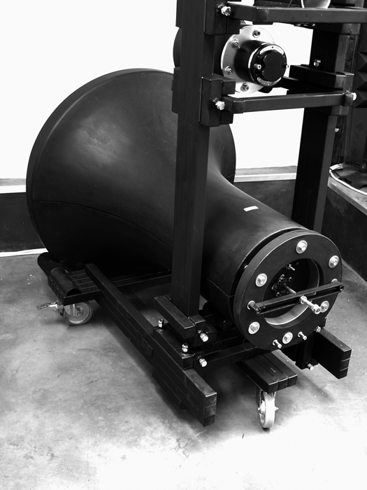
Above : The assembly is bolted to the horn. Once the bolts are "tight", the gap between the clamping ring and the rear face of the horn will remain; this is to permit compression of the felt seal between the mating surfaces of the chamber and the horn, as well as putting a resonance-canceling load on the cylinder. It also permits adding a longer piece of sewer pipe should a larger rear chamber volume become necessary. So, ready to start tuning!
jd*Rerurn to Romy the Cat's Site