Rerurn to Romy the Cat's Site
In the Forum: Melquiades Amplifier
In the Thread: The 6E5P tube data.
Post Subject: I probably shouldn't post these...Posted by hagtech on: 2/21/2008
But here it is. I made this monoblock fit into less than a square foot. It is tight. I use Hammond iron throughout. Their stuff usually works pretty good for power supplies. I have some photos at my blog.
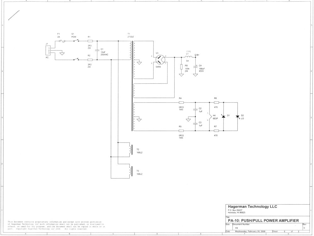
The power supply is very straightforward. One section of LC on rectifier is enough. I forget how much ripple there is, something like 0.2Vrms.
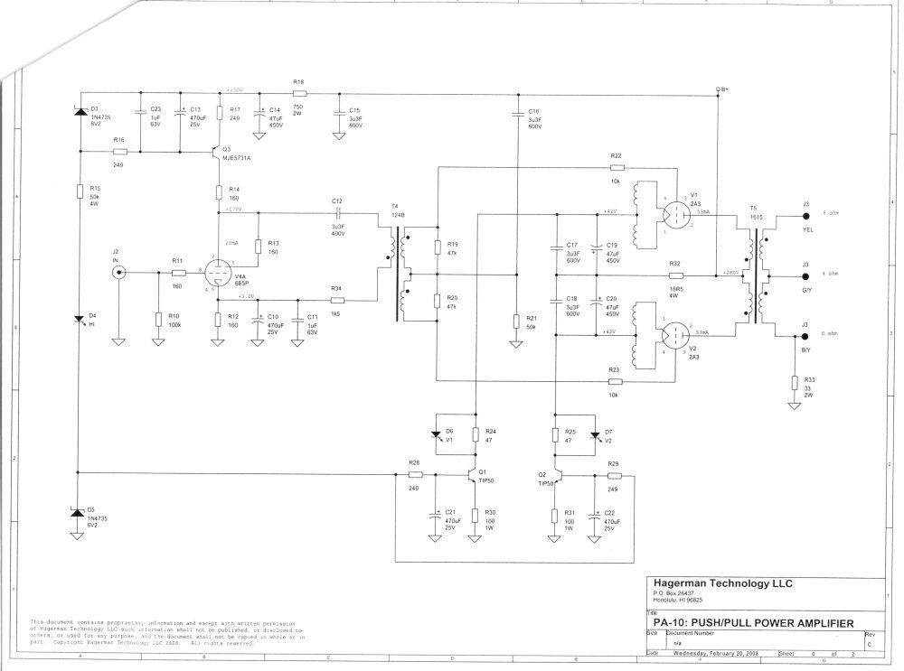
It looks like a mess, but it's not. The output stage is drawn push/pull. The non-feedback type transistor CCS in each tail make sure there is perfect dc flux cancellation in the output tranny. Cathodes are tied together at ac via C19 and C20. Thus, your basic differential amplifier. Here's where the trick comes in, R32, if set to zero ohms, effectively shorts the cathodes to B+. In this case, we have two independent SE amps of opposite phase. By adjusting R32, the ratio between SE and PP can be set for lowest distortion. I believe Western Electric came up with this in the 1930s. My connection is different because of the CCS, which they didn't have.
You'll not R21 sets the common mode voltage of the grids to zero volts. C16 couples the B+ ripple directly into the grids. Thus, the voltage seen by the tubes themselves remains constant. This is a very effective cancellation of ripple. You can't believe how effective this is. There is also common mode cancellation in the output tranny. So bias on tubes is constant, there is no operating point modulation and mixing (IMD). The cathodes are free to follow the grids.
The driver is a triode strapped tetrode, per Dima and Romy. I run it with a CCS load, again, no-feedback transistor source. The output impedance of the 6E5P is roughly 1.5k, with cathode grounded (I am using cathode bias). I discovered that the interwinding capacitance of the IT gets very unbalanced and assymetrical if R34 is zero. Hence, I balance the primary drive impedance-wise by adding the 1.5k in series. Ok, so now we're driving a 10k:90k IT with a 3k source. Should be ok! There are other issues with the IT, such as non-interleaved secondaries (one is outside the other, with higher dc resistance), resulting in two values of leakage inductance, and two main self resonances. One at 26kHz, the other at 74kHz. My best transient response occurs when I split up the damping. I run very high grid resistors of 10k, which when combined with the grid capacitance forms an RC snubber for the upper resonance. The lower one is then tackled by the 47k. These resistors are snubbers. I could put them inseries with small capacitors resulting in higher LF gain, but I don't like that. I figured best to keep out as many capacitors as possible. Anyway, it works. I tame the HF response to an almost perfect Butterworth. The 10k grid resistors also limit how far it can enter into A2. That's why the overload condition looks so nice. Now, HF rolloff is very clean, once it starts dropping, it just keeps falling. No ultrasonic wierdness.
I will probably use these amps using the 4 ohm taps. That still delivers 5Vrms at output. Enough for my small room I hope.
jhRerurn to Romy the Cat's Site