Rerurn to Romy the Cat's Site
In the Forum: Melquiades Amplifier
In the Thread: 6 Channel Version of Super Melquiades
Post Subject: The Super Milq’s input: electrical perspective.Posted by Romy the Cat on: 11/24/2007
 op.9 wrote: op.9 wrote: |
Could you help me understand your biasing scheme with this version? I thought I understood the original Milq circuit - but the only channel that looks like that to me is the D channel. I don't get A and B at all! what is the 50 ohm resistor doing? is it just a grid stopper? I assume you can adjust bias and 0v at input in each stage - but don't the two red legs (on channel B for example) work against each other?
|
|
Sure. Let live aside of idiosyncrasy of sound with gas tube driving fixed biased 6E5P. I have written about it in many places:
http://www.GoodSoundClub.com/TreeItem.aspx?PostID=5533
…and it would be totally different subject.
Let look at the Super Milq’s input just from purely electrical perspective. The basic premise is to get rid of a DC blocking capacitor at input. To do it we pit a series dose ohms resistor and then apply a contra-collage on another side to keep the DC balance at input at zero volts. Then we need to put at each channel own filter.
Here is the initial filtering idea.
I intentionally kept all drafts on the site to show progress and how one thing flew into another. Eventfully the series capacitors were replaced with RL filters and it make too many series resistors in signal pass, so the objective was to combine the filtering and biasing duty of the resistors together.

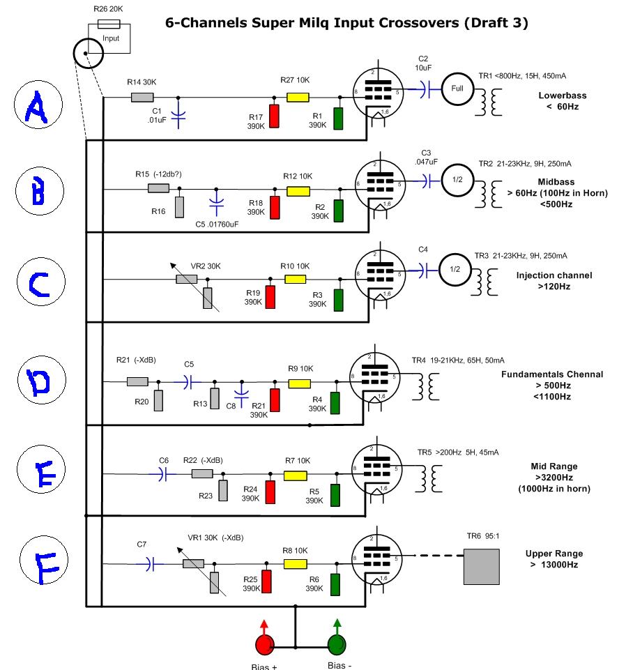
So look with what we end up:
Channel A: Has RC (substitute for L) filter at input and the 30K filter resistor is used as yellow biasing resistor. Look at the Draft 3. R14 and R27 are the same resistor and if so then we do not need R17 (red), the purpose of Red resistors is apply positive contra voltage on the left side of bias resistors but in the final draft on the left side of 30K resistor there is a common B+ voltage share be all channels. Surely, since we have much less positive voltage “sipping” through the new bias resistor (30K is more then 12.1K) then we need to apply much less negative voltage to the grid, or to increase the value of greed resistor. The 50R resistor is grid stopper; it might or might not be there – does not matter for THIS circuit. (The need of grid stopper for fast tubes is another subject all together)
Channel B: The identical story with the Channel A only instead of 30K series resistor we have a voltage divider that from a prospective of filter/bias is the same fixed series resistor. Pay attention that of I can the cable on the left side of the divider, disconnection the Channel B then I would need to change value of the Red 402K resistor at the bottom of the image as the total balance of positive (coming from 402K resistor) and negative (returning back from each channel) will be changed.
Channel C: this is practically standard Milq configuration with L-pad at input – there is not filter in here. You would ask me why I did not use the same approach as I used in Channels A and B – getting rid of Yellow and Red and letting voltage to pass via the attenuator to common positive. The reason is because my L-Pas is laden type, what has constant input impedance and variable output impedance. So, the circuit balance the 0V dc on left and right from the L-pad, making the channel DC do not care about the L-Pad. If in my L-pad I would flip not 2 resistors but 4 and the output impedance was constant then I would employ the same approach as I did in the channels above.
Channel D: This is quite complex. We can’t used the approach as above as the DCR of filtering coil is too low (250R) and the negative bias voltage shorts itself to ground via the coil. So, we need here a fill scale biasing Yellow resistor to keep the tube happy. What happened at left side of the Yellow resistor? Some voltage comes from positive bias, via 36.6K resistor and across 250R of coil to ground. So, why do we care, we juts adjust the voltage of common positive bias and it will be it.
Channel E: The RL filter, the situation is identical to the Channel D. It might be a concern that I have we have too high series resistance in a grid chain. In practice is dos not sound as HF-challenged. That impedance with Miller capacitance of the 6E5P makes ~ over 100K low-pass filter … not so damaging for a fast, oscillation-incline tube.
Channel F: It has input cap that does not transmit DC, so we should not vary about anything and juts run one green resistor with negative bias supply. However, some voltage drift via coil to ground, passing through the L-Pad with variable output impedance… Eh, Not good! So we need to put a Yellow “bias stopper” into the game and to get 0VDC on the left side of the Yellow resistor. Then positive will not flow to coil because it will be blocked by the cap and negative will not flow anywhere because it balanced by red resistor. This way flipping the L-Pad affects nether bias nor impedance. Not that the L-Pad has constant input impedance against which the CL filter is written (it is Bessel). It was very important and a change if the attenuator impedance would lead to change of crossover point and subsequentual throwing the tweeter off the time aliment.
Rgs, Romy the CatRerurn to Romy the Cat's Site