Rerurn to Romy the Cat's Site
In the Forum: Audio For Dummies ™
In the Thread: Get, or made up a tube tester, it’s necessary
Post Subject: Triode CurvesPosted by hagtech on: 1/22/2007
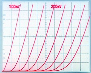
Ok, here's some calibrated sweeps. I ran the tetrodes in triode mode, with G2 strapped to plate through a 100 ohm resistor. First up is the western 6e6p.
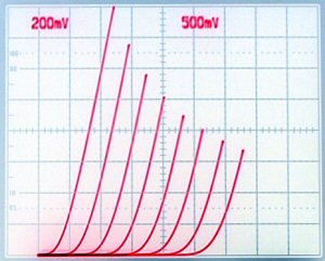
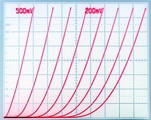
I then built an adapter card that sweeps both 6e6p at same time. But on my good scope it's hard to see what is going on, as the "dotted line" function was not hooked up. Easier on my cheap scope. Makes dueling traces easy to pick apart. So instead, here's one at a time. This one is the '63.
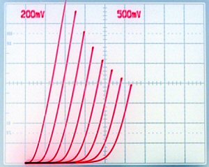
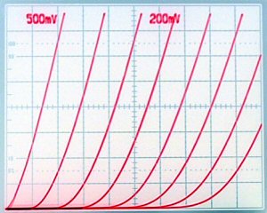
And the '62, dark one. Plate is 50V/div, current at 5mA/div, 1V grid steps.
Note the '63 has much higher gain. The horizontal spacing is basically "mu". Interestingly, the 6e6p has lower gain than both of these. To me, the curves are beautiful. Spacing is relatively constant, indicating superb linearity. The tube can also push huge amounts of current. That is not shown here, as I zoomed in to a 5mA/div scaling. Previous posts were at 12.5mA/div. The high slope of the curves means a very low output impedance.
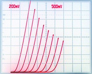
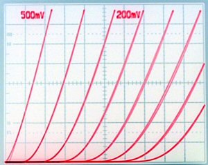
Each tube here appears to be very good. I see no anomalies. There will be sonic differences, as a circuit biased for one of these will be sub-optimal for the other two. This is a pretty large sample-sample difference.
Ok, next is my attempt at a 6c33. Clearly there is not enough grid voltage to sweep this tube. Again, 50V/div horizontal, but 25mA/div vertical. The sweep cuts off at 200V plate because there is not enough grid volts. Lines are at 10V/div. Starting at 0V.
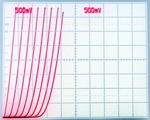
So I zoom in. This is at 20V/div plate. So it still gets up to 200V. Note the distortion characteristics. One, the curves gradually get closer together with more negative grid voltage. Two, the slope changes. The spacing indicates a nonlinear gain when used in circuit. The slope means output impedance is changing. Both will affect performance in an amplifier. Oh yeah, I wired the tube up to do only one half at a time. This is the 1,2 heater.
This is same "new" tube but with "7,6" heater pins engaged.
A composite tube would be merely the sum of the currents. Not a good match between sections. And now the same thing for the "old" tube.
and
The older tube has less gain. But something really funny showed up. And I am not used to seeing this. On the 76 side, notice the loop in the curve! This must be some hysteresis. The curves are generated by ramping plate voltage up, and then back down. Generally, the two curves fall on top of each other. In this case, something split them. I can sweep slower and faster. And the loop (I forget already) I think is larger at slow tracing (which is supposed to be more accurate as it gives the grid step more time to settle). My guess is that the loop might be caused by grid current. I dunno. However, we may have stumbled upon some practical indicator.
jhRerurn to Romy the Cat's Site