Rerurn to Romy the Cat's Site
In the Forum: Melquiades Amplifier
In the Thread: Planning my DSET
Post Subject: R4 is the CulpritPosted by anthony on: 7/26/2020
Thanks for your help Romy. Have a look at this (barely legible) sketch so we have a common reference:
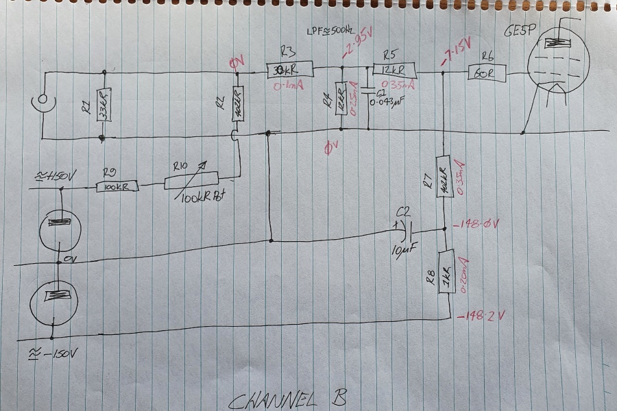
This is Channel B First Stage bias circuit. All is identical to your published schematic apart from R9 which I had to increase to get the other stages to bias up around -4V. In red are my voltage measurements at those points with the current calculated according to the nominal resistor value: they seem to correlate. Note that R4 has a voltage drop across it and contributes -2.9V to the bias for the 6E5P. This is different behaviour to all of the other channels where the crossover filters do not impact the bias for the first stage tube. Channel B filter is unique in that it has a shunt resistor R4.
If you recall Channel A has foregone the 12kR resistor (R5) and uses a larger 1M R7. If I did this, I could remove R4 entirely, swap out C1 for 0.01uF and retain the same low pass filter frequency. It is essentially the same as Channel A but wil a different LPF. See below:
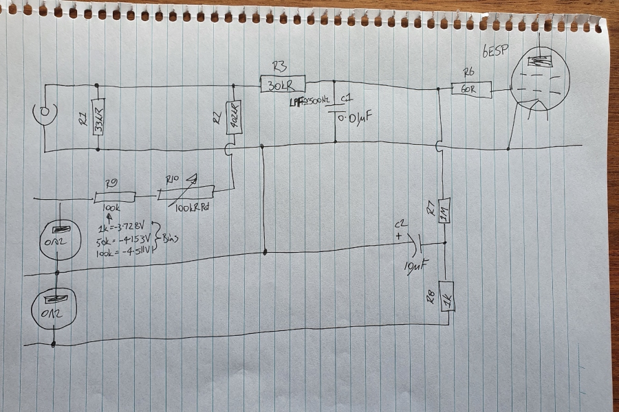
R9 can then be adjusted to get the ideal bias voltage, and all three channels on this bias circuit (A/B/C) will adjust by the same amounts.
Rerurn to Romy the Cat's Site