Rerurn to Romy the Cat's Site
In the Forum: Melquiades Amplifier
In the Thread: Planning my DSET
Post Subject: DSET amplifier is designedPosted by anthony on: 4/5/2017
It took a LOT of time in CAD using what I had learnt from building the power supplies and then adapting it to match the requirements of the rest of the system. I have decided to mount the DSET on the horn stack and direct connect the speaker cables. This makes the design quite difficult in that have to work around the pillar, provide adequate horizontal and vertical vibration isolation and still meet the component layout requirements for a sound assembly.
Did I say I spent a lot of time in CAD sorting all this out...I did...months...in the end much, much more time that I thought was reasonable for the task. There were several iterations along the way and talking to different people and receiving the intended parts to be included in the chassis meant alterations to the design were prudent. For example, in my second or third to last design iteration I finally weighed all of the components and estimated the steel weight and realised that the amplifier was going to be a two man lift and that if I wanted to tweak anything in there I did not want to be pulling it off the horn stack, carrying it downstairs, working on it, carrying it back upstairs and reinstalling it...I needed access to all the most likely tweak areas while it was still sitting on the horn stack so I could put down a dropsheet and bring the soldering iron up to the amplifier. Afterall, if tweaking something is that much of a logistical exercise you can guess how much fine-tuning will be done...none!
I like simple designs for complex things and in some way I think that I have achieved that, but in other ways I certainly have not. I wanted a clean top with only valves showing, I wanted it mounted on the horn stack, I wanted all the cable connections pointing vertically rather than horizontally and I wanted all the dials, knobs and meters located either front or back but not at the sides. The build will be complex with multiple levels of components not to mention the sheer weight involved, and I think that I have a good logical layout with enough room for various components. When the 'package' gets too heavy during assembly I will just install it on the horn stack and the bring up various pre-assembled portions for final connection in-situ.
Step one of the build will be the floor with associated cooling fans (filtered!) and vibration isolation.
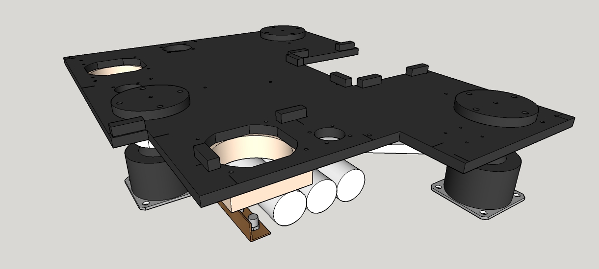
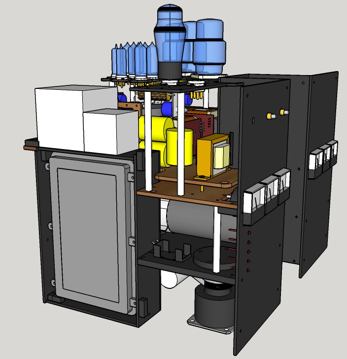
Next will be the filter caps, output transformers and bleeder and service circuits:
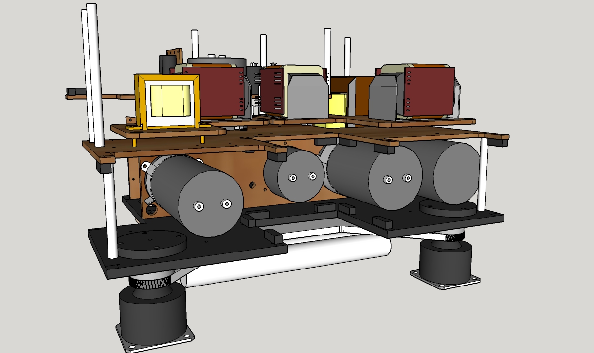
The OPT's will sit on small sorbothane isolated vibration platforms. The internals are mostly aluminium so the OPT's will not couple to them. The floor and all external panels with exception of the top panel are steel.
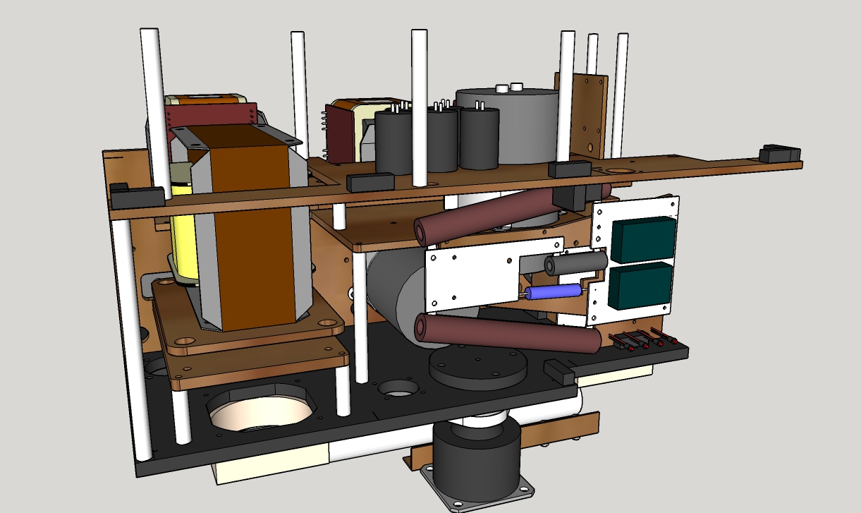
Then the meters and knobs will be bracketed and the beginnings of the PLLXO's installed.
The two white boxes at the top of the image below are filter chokes for the PLLXO's. In the end I have opted (at the winders insistence) for them to be potted in heavy steel shielding rather than mumetal, which makes the overall product much larger, but also less expensive and more robust. The HF filter is both magnetic and EM shielded by steel and an aluminium EM box.
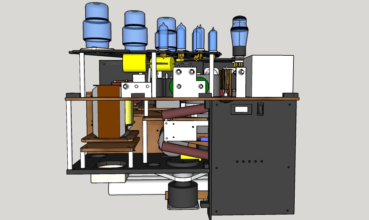
Sometime during this stage I anticipate that the amplifier will be mounted on the horn stack. Some final assembly and it should all look similar to this:
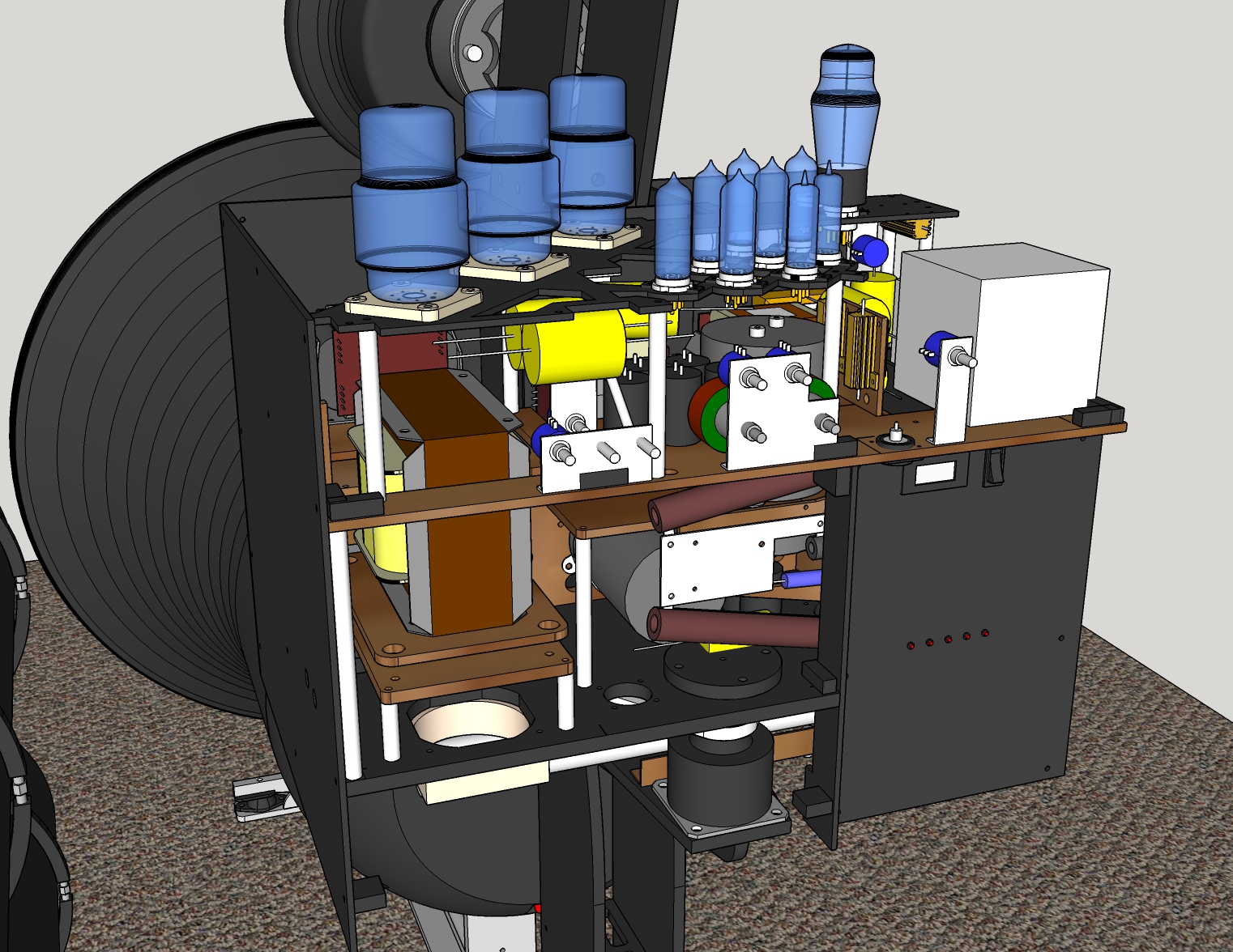
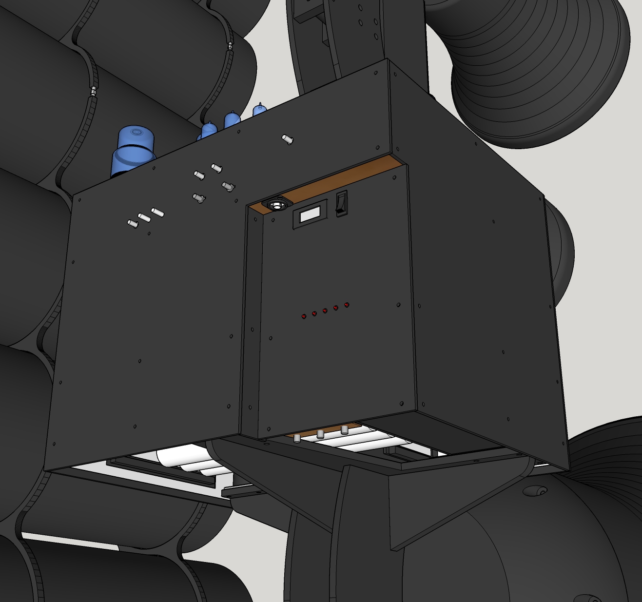
Notice in the image above that the tubes sit by themselves on a 'rafter' that can be exposed by removing the top panel. Remove the back panel also and I have reasonable access to the PLLXO and other important areas that I am likely to fine-tune. All of the pots on that back panel are actually installed on brackets inside the amplifier and I can just remove some knobs, undo some screws and the amp is still perfectly operational with the panel removed.
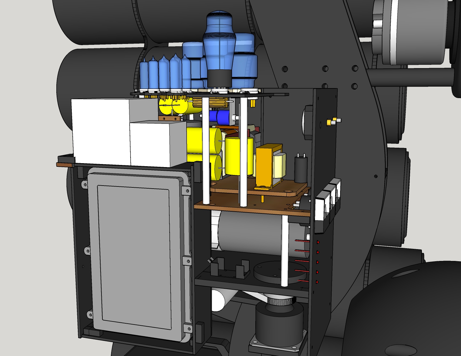
Looking from behind at a closed up DSET, you can see that the BNC connector to accept the interconnect is vertical rather than horizontal. I did this because of the height at which the amplifier will sit and the stress that this will place on some cables. I have also added a battery powered digital multimeter and switch so that I can check the DC Offset from time to time. This way I don't have to connect up a multimeter to check when I am curious or whenever I change regulator tubes. When I am finished I just flick the switch that removes the battery power and there are no deleterious affects to SQ (my dac has this same arrangement to check DC offset). I had considered using the same battery powered digital voltmeters to check plate currents but in the end opted for the more aesthetically pleasing analogue meter.
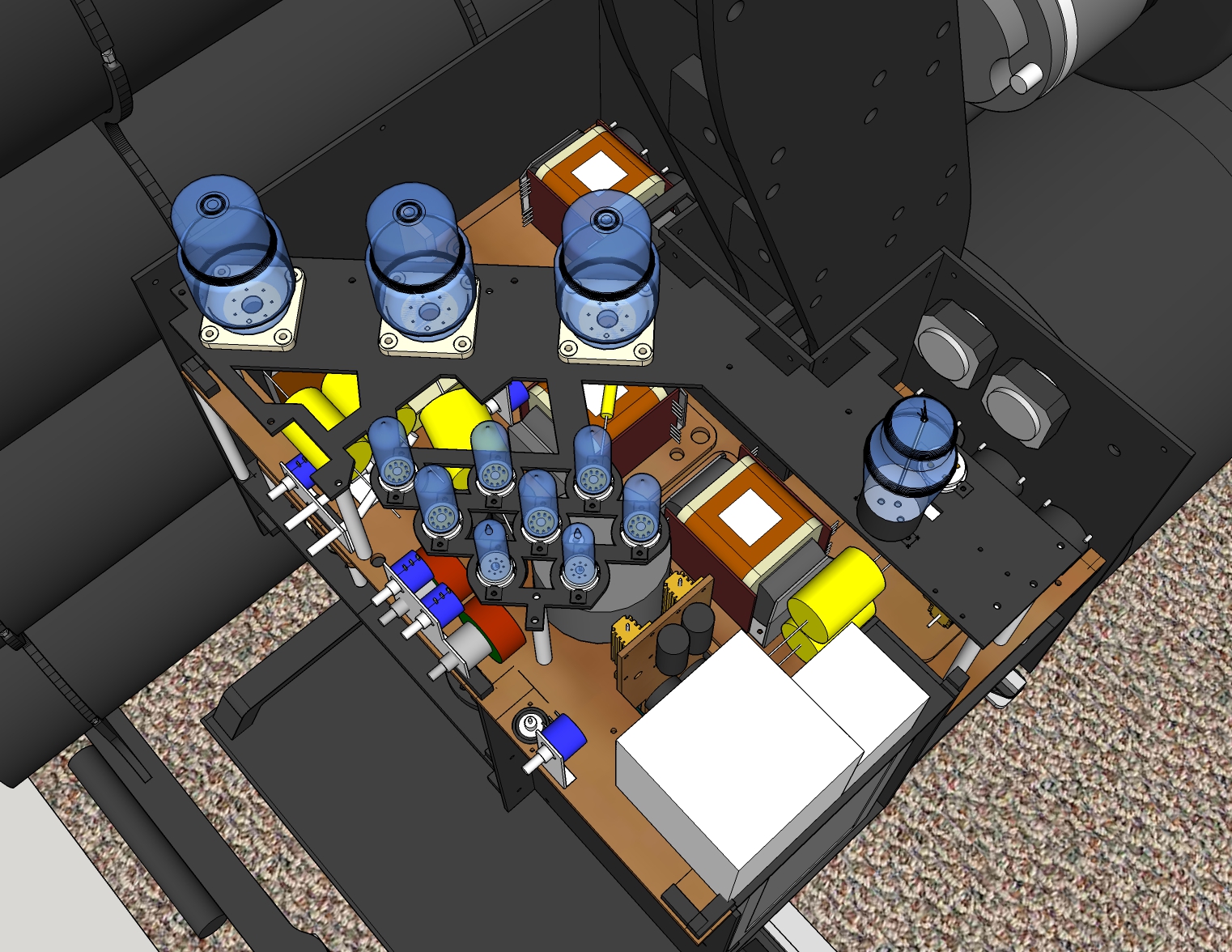
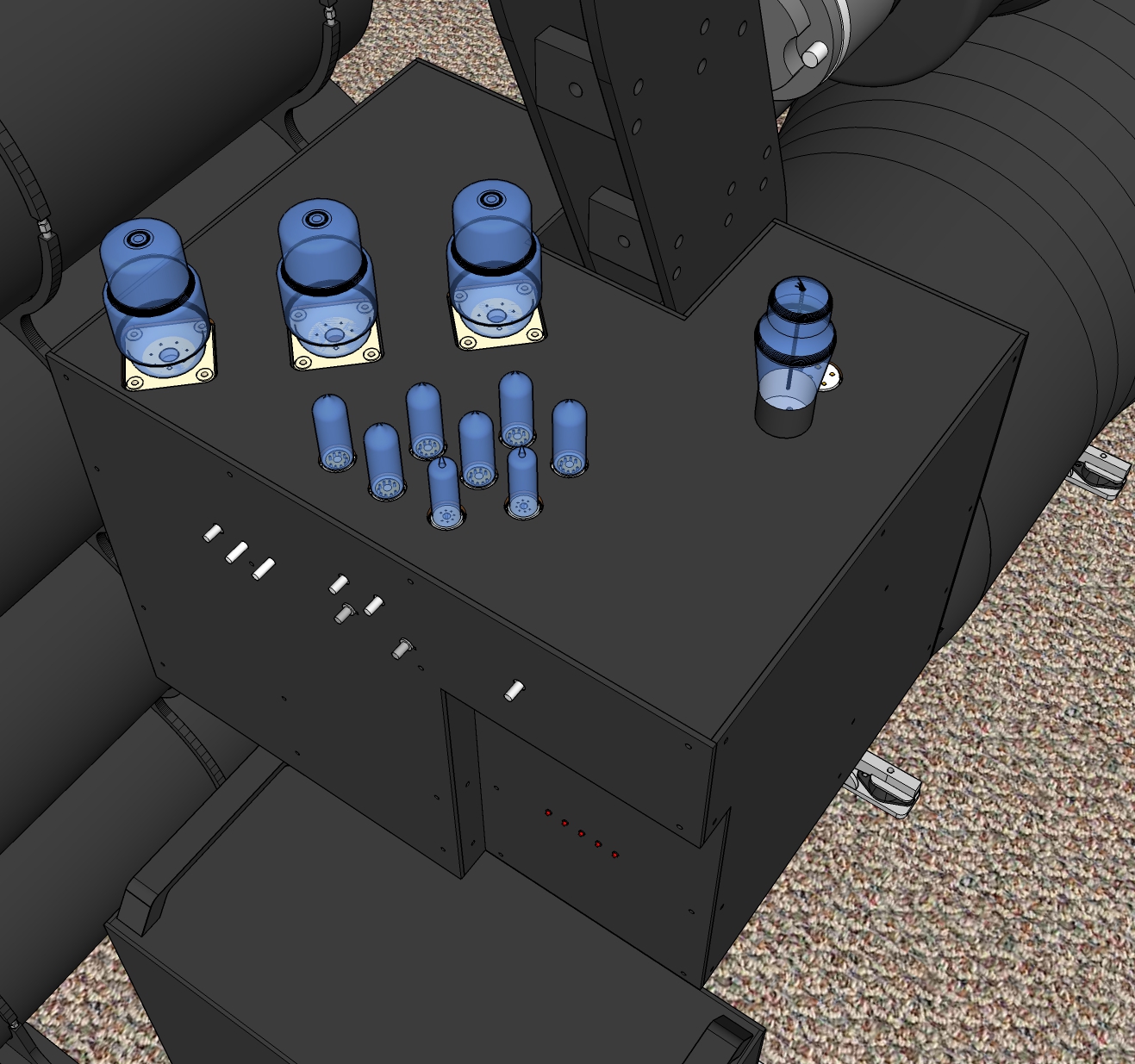
On the image of the top plate below you may be able to make out the air venting around the base of all of the tubes. The two case fans in the floor of the chassis push air up through the case and the major exit point is around the valve bases. Hopefully the rest of the chassis is sealed up tight enough that enough air exits vertically from the top plate to keep everything cool inside. It is for this reason that I have included two 80mm fans in the design just in case I need more oomph...I can opt to run either one or two depending on how the situation is when it all is assembled.
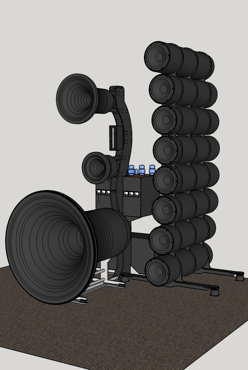
And finally an image of the system concept at this point in time:
Guys, if you have any constructive criticism or tips please chime in.
Rerurn to Romy the Cat's Site