Rerurn to Romy the Cat's Site
In the Forum: Analog Playback
In the Thread: The last phonocorrector: “End of Life" Phonostage
Post Subject: My assaultPosted by N-set on: 8/30/2011
fiogf49gjkf0d
After going through the anal pains of the Image Gallery upload (it is so
huge now that my browser slows down 10000x times loading it and it ocasionally kicks
my router out of this world; can we do something about it?), here are some pics
of my assault on the Pussyfied EAR 834. This is basically a blatant copy
of Romy's unit, with some minor additions and a bit different layout.
It's not finished. It's soldered and statically tested (OP points etc),
but I'm endlessly waiting for the SUT's from Tribute so no idea when I'll start listeting.
I also want to go through the PSU with a scope to see how it performs.
Here is the PS block top view:
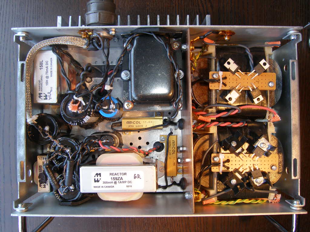
The power supply transfromers are separated by a grounded copper plane.
The transformers are form a Polish supplier Telto, custom wound to my specs
(windings on separate legs, double screened with copper foil)
Not recommended! They become warm and the HV one buzzez a bit...despite being
3x overseized. The trannies as well as all the open chokes are surrounded by a copper
band to supress some of the garbage they emitt.
Here is the bottom view:
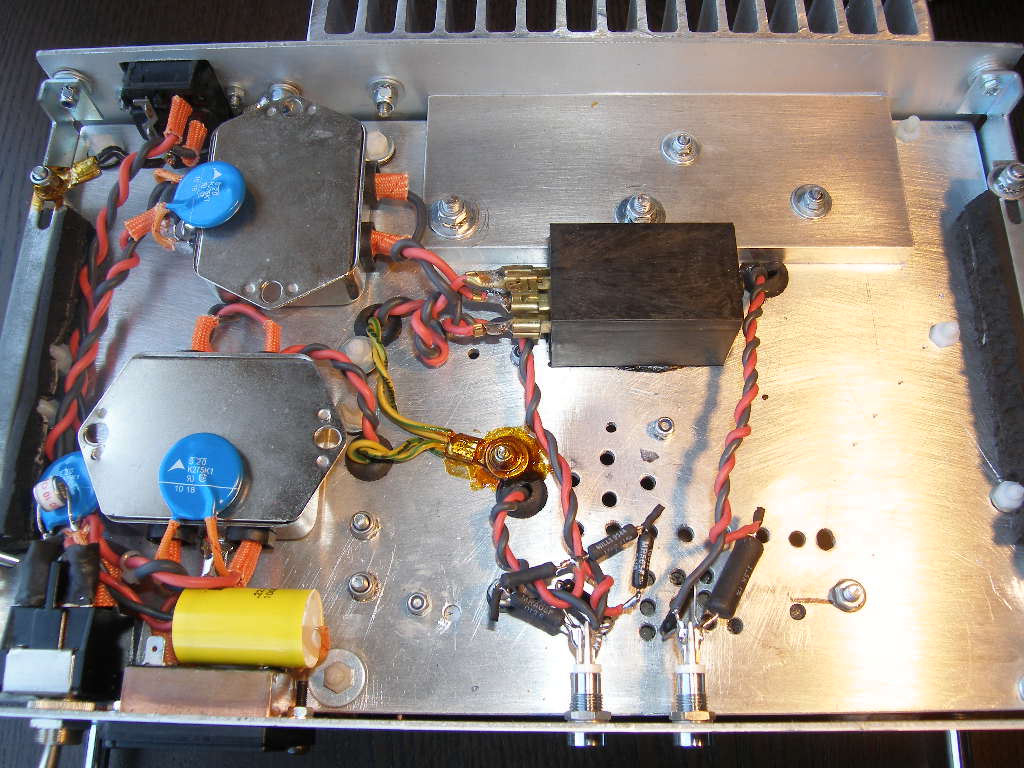
Everything, following actually Romy's idea, is mounted on a alu plate using industrial silicone
and screws. Nothing vibrates and the feeling is of being acoustically quite damped. There are
commercial RFI filters +varistor per each tranny, a varistor + gas arrester at the input,
NTC on HV, time relais on HV, two pilots, and an hour meter bypassed with 0.22u cap.
Paul will recognize his saturated shellac trick  (still not everywhere done--have to scope the unit first).
Here is the top view of the signal box:
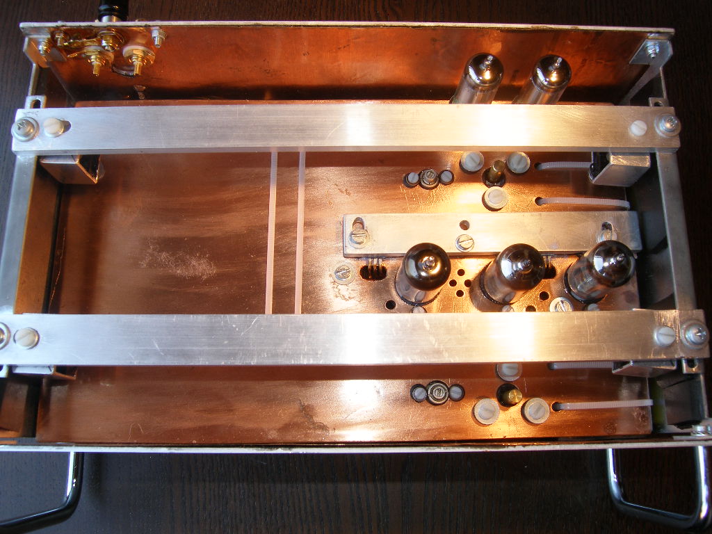
The fron and the rear panels are covered with a plastic-protected 0.3mm copper foil and so will
be the top and the bottom covers. This should create a +/- "hermetical"
electrostatic screening.
The main changes wrt Romy are 1) a CCS heating has been implemented with
a big pain as to the soldering/layout (the regulators are below the
middle alu bar) It was my intellectuall capricio which costed me endless hours of work, hope it all
burns in hell after I die; 2) The VR's are close to the tubes; I somehow feel better having the regulation elements
close to the regulated ones, so that the pickup on the umbilical have some chance to be cleaned by VR's too.
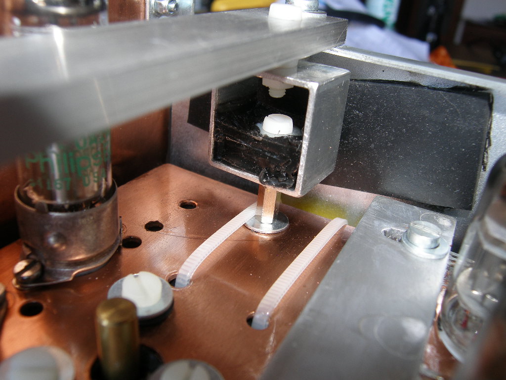
3) The 1.5mm thick plate (protected with some plastic spay) is suspended on homemade
suspensions (I saw prices of commercial ones and said "thank you"):
4) The last filtering stategs of the heating/bias is also on the plate. Here is the general view
of the mess I've created:
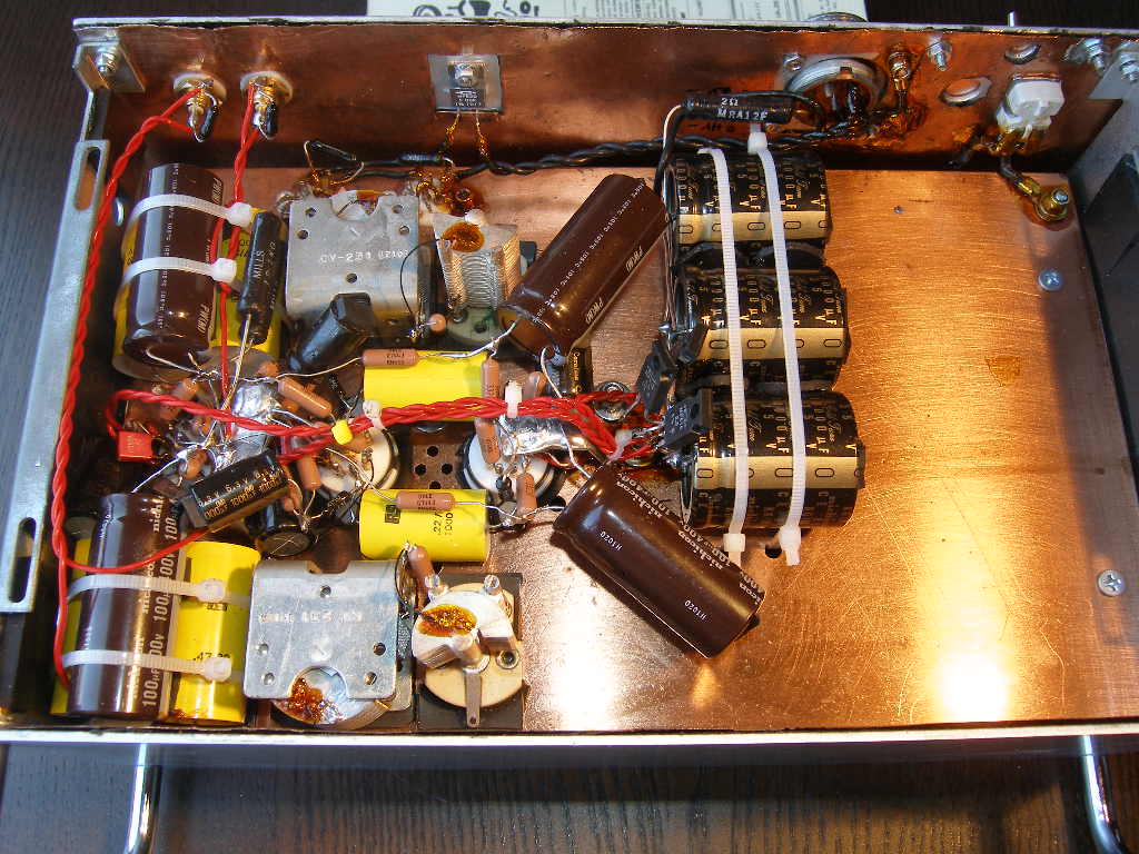
If you don't like my layout, you are not alone, I don't like it either 
I've soldered directly to the rotor of the air caps. One was easy as it has silver coated blades,
the other one has alu blades so a special flux and a 200W iron were needed. Let's see how it
works with time (corrosion etc)..
I have been trying to find a method
to solder to the plate directly, but failed, resorting to bent and solder coated 1.5x10 mmcopper strips, bolted
to the plate and protected with the shellac (there are 2 of them--at the input and between 2nd & 3rd stages).
All that resulted in resistors being quite lifted above the ground plane. Very much not recommended!
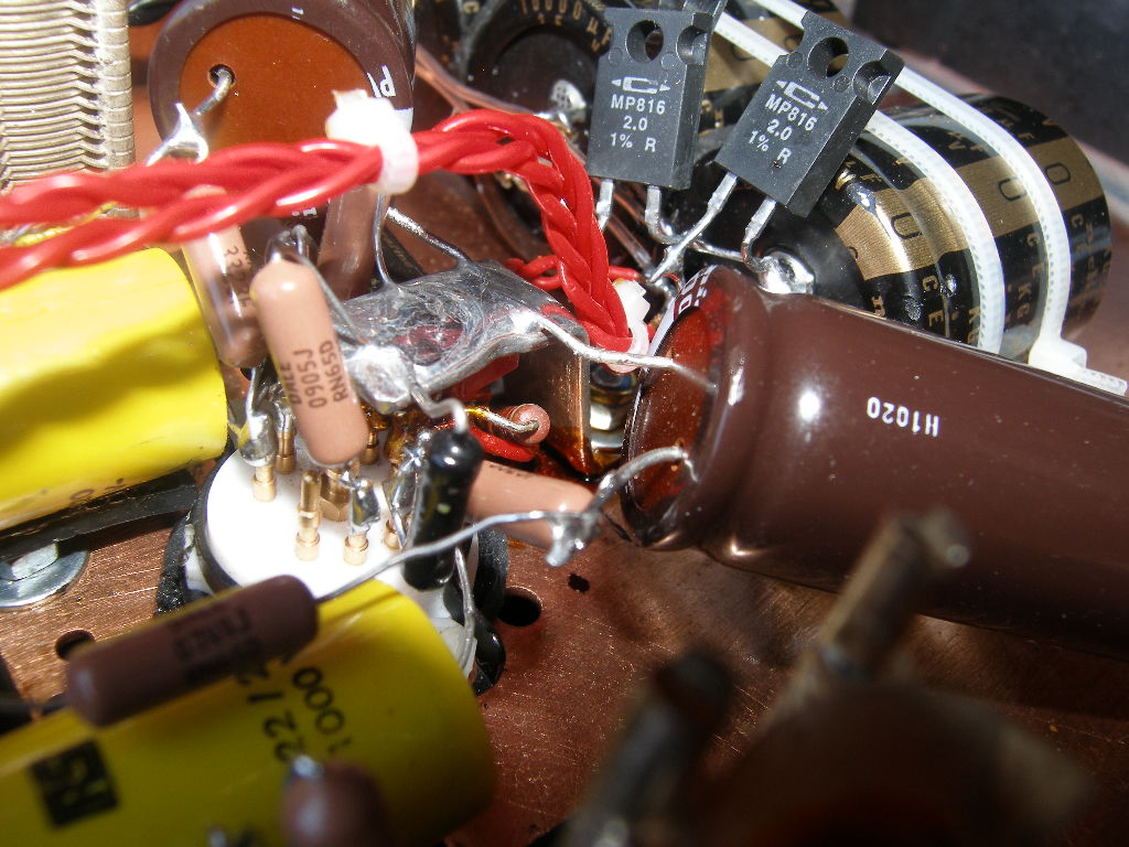
This is one of the mass terminals:
And some more boring details:
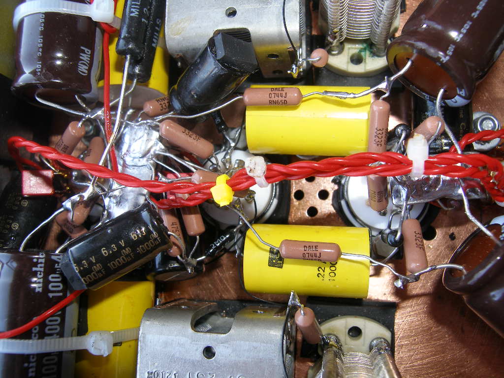
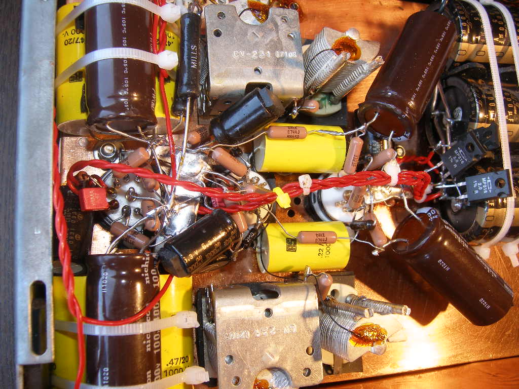
The wireing is cardas (let it burn in hell for being so infinitely stiff and such a pain to solder!!!)
The thin ones are the tonearm 33ga wires to let the caps move. The air caps, the coupling caps,
the heater caps, and the signal tube sockets are mechanically insulated with sorbothane
(it actually looses some chemicals which melt a bit the copper plastic cover, damn sorbothane).
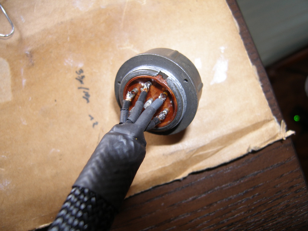
The PSU and the signal blocks are connected by a homemade umbilical with 15.5ga cardas
and some new production Polish military-style connectors. Very much not recommended,
it's better to pay the $$ for the real amphenol rather than those mediocre copies.
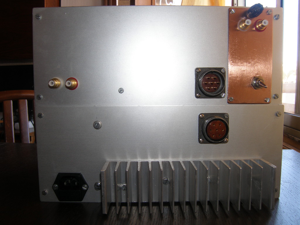
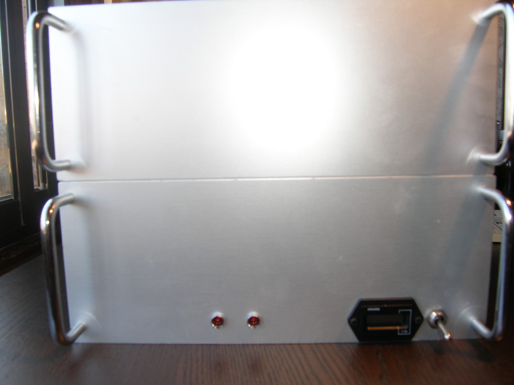
The fron and the back view of both units (without the covers):
After I recover from the horrors of the image gallery, I'll try to post the actual schematics of what I've done.
There are some minor changes mostly because of my mistakes in PSU design, and a
lottery of the PSU trannie outputs with a desire to maintain the real choke operation.
The next step is to try to listen all that mess and see if the months of hard work were worth it...We'll see.
Rerurn to Romy the Cat's Site