Rerurn to Romy the Cat's Site
In the Forum: Audio Discussions
In the Thread: Initial thoughts about new/old Lamm ML2s
Post Subject: Bi-amping (L2) & Images of new sockets (ML2)Posted by jessie.dazzle on: 1/30/2011
fiogf49gjkf0d
Regarding L1 and L2 outputs and bi-amping:
Romy wrote:
"...The unfortunate part is that if you still intend to run a dedicated cable to your let say LF section and if you use Lamm preamp then you can’t... his preamps (L1 and L2, I do not know how about L3 but I think it will have it as well) have single ended and XLR outputs and fully balance topology... So, when you flip the absolute phase on Lamm preamp then your XLR output and RCA out become in opposite phase..."
This is true.
"...Go read all reviews ever were written about L1 and L2 and see if any of those Morons ever noted it..."
One did; in reviewing the L2 preamp, John Atkinson (Stereophile) wrote:
"...The absolute polarity was preserved from both sets of outputs with the front-panel switch set to "0 degrees," confirming that the XLR jacks are wired with pin 2 hot. Setting the polarity switch to "180 degrees" inverted the unbalanced output but not the balanced output..."
From the manufacturing point of view there may be a good reason why this is the case, but from the consumer's point of view, it is not ideal.
In a bi-amped system running an L1 or L2 preamp, if one of the pairs of power amps happens to be Lamm M1.1s (and the later versions of this amp), it is possible to reverse the phase of the entire system, as the M1.1 offers the possibility to invert phase (and therefore bring it into phase with the other pair of amps) via a shorting plug. This is how I get around it; obviously, inverting phase is not something I do often.
Back to the ML2; since the XLR and RCA inputs on the ML2 power amps are wired in parallel, the XLR inputs are in fact not balanced, and this is stated in the operator's manual.
Regarding the Teflon sockets:
Romy wrote:
"...I do not know how the contacts are made in the Teflon sockets..."
The part that grips the pin is made of several tiny contacts. I don't think they are gold-plated; in any case, gold would likely not fare too well in the presence of the heat generated by the 6C33C.
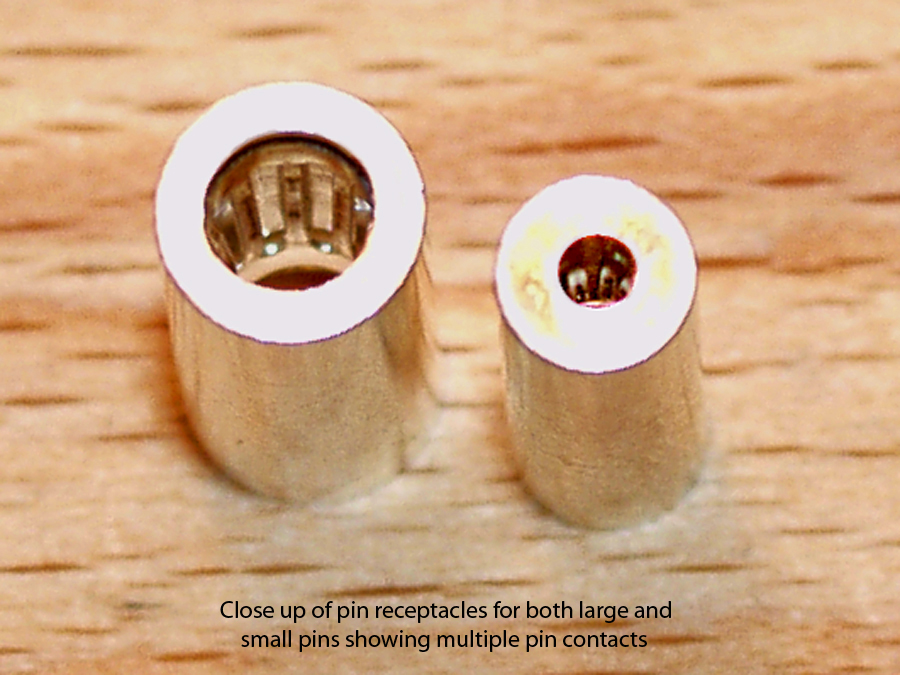
"...For the small currents Teflon is very good as it stress the contacts to be very tight. For the tubes like 6C33C the Teflon that would push the contact to be tight is not good idea as the coals run much hotter and if they are surrounded with Teflon then they would not be ventilated well. Still, I did not play with them and do not know how they made..."
Image below: In the case of the Teflon sockets for the 6C33C, the Teflon plays no roll in clamping the pin; there is in fact a generous gap around the pin receptacle and all clamping force comes from the springiness of the metal contacts, which are confined by a hollow cylinder.
Next two images: The pin receptacles are composed of threaded parts, which, in my opinion, should be soldered as one to improve both electrical and thermal conductivity between the individual parts, as well as keeping them from coming loose over time.
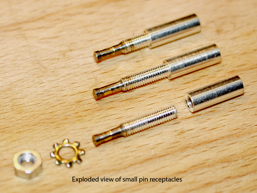
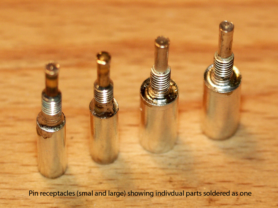
Image below: Here is the problem with these sockets... The threads of the large pin are not long enough (not enough of them protrude through the Teflon base) to allow proper threading of the securing nut. Threads on the smaller pins are longer and the smaller assemblies can be adjusted to compensate, but as this is not an option with the large pin; thickness of the Teflon base must therefore be reduced by at least 1.5mm.
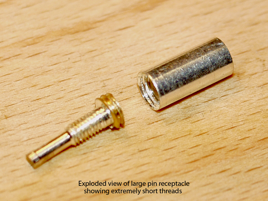
Image below: Showing material that needs to be removed to allow for short threads of large pin.
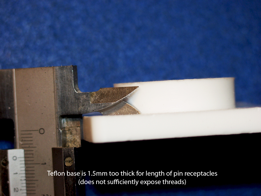
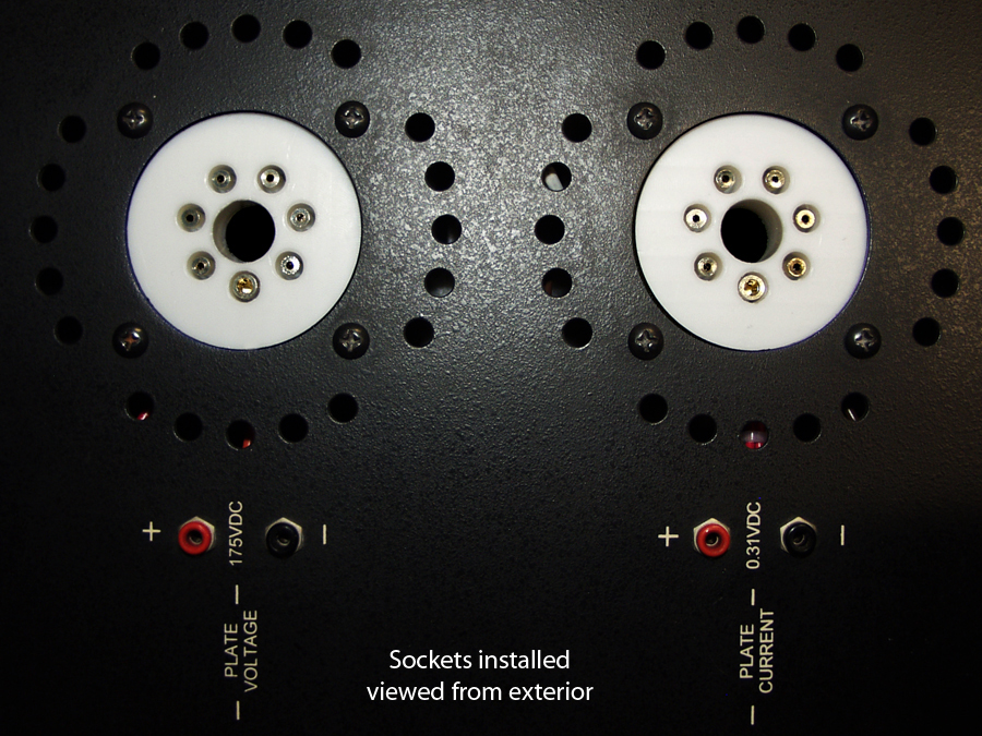
Image below: Fully assembled after Teflon base has been reduced by 1.5mm; note, even after reduction in thickness of base, there are still no excess threads protruding past the securing nuts. In the case of the ML2, the four chassis mounting holes in the Teflon base must also be enlarged.
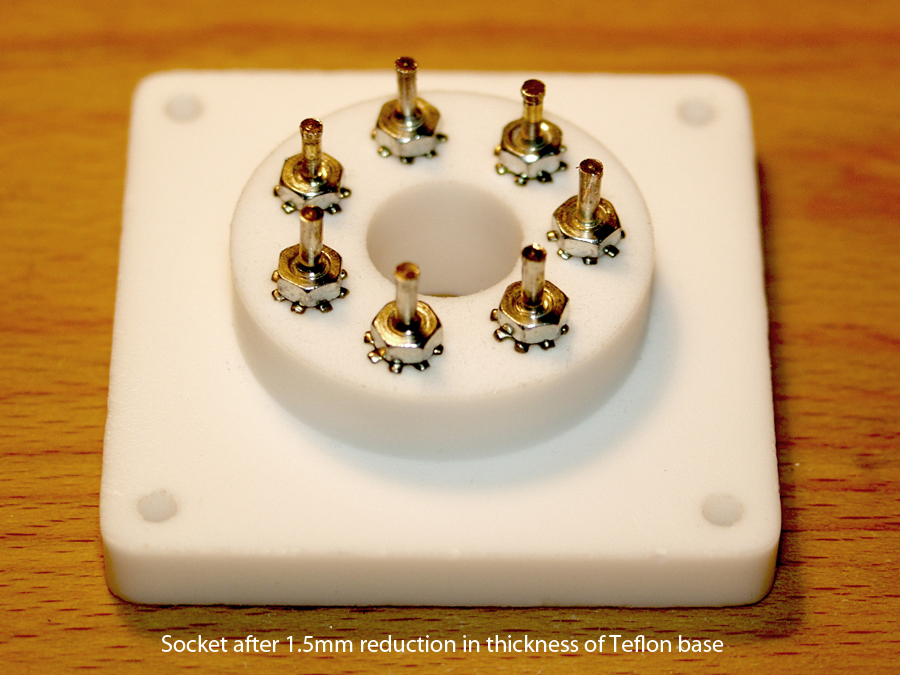
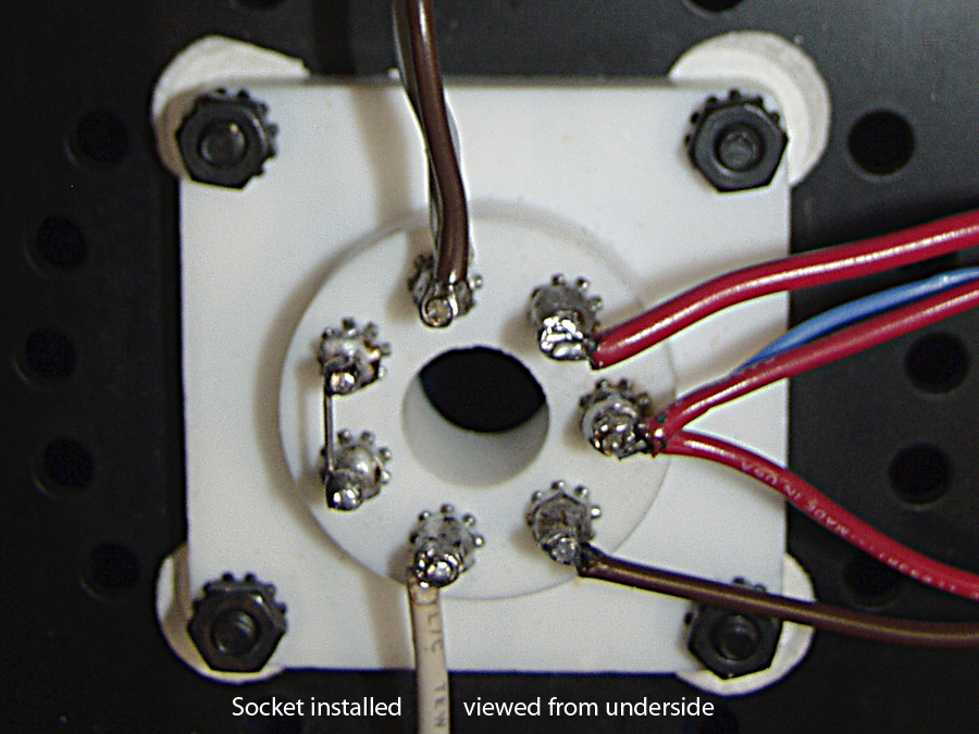
Image below: New sockets have pin receptacles closer to the center of the socket... Lamm rightly leaves no excess length, so getting the original wires to reach the pin receptacles is tricky.
In spite of the work necessary to correct the thickness issue, I'm very happy with the results and would in fact recommend these sockets. I do nevertheless have to admit, considering the price paid (something like $38 each plus shipping and customs), that it is reasonable to expect a finished product. I assume these are among the first that the manufacturer has produced for the 6C33C, as the thickness issue could be easily corrected during future production.
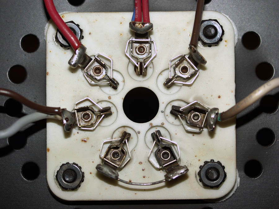
About the "guy out there" who does not like the Teflon sockets; look at the reasons he gave; "difficulty in desoldering" and "darkening of the metal". This is silly; solder typically melts below 400 °C (752 °F); the type of metal used for pin recepticals will not chang that. About the darkening of the metal; if you want to see darkened contacts, take a look at those of the original sockets (image rotated 90° counter clockwise relative to image above):
jd*
Rerurn to Romy the Cat's Site