|
Posted by jessie.dazzle on
08-03-2007
|
Below are some images of what I was thinking (my apologies for the long load time) :
Please feel free to laugh!
jd*
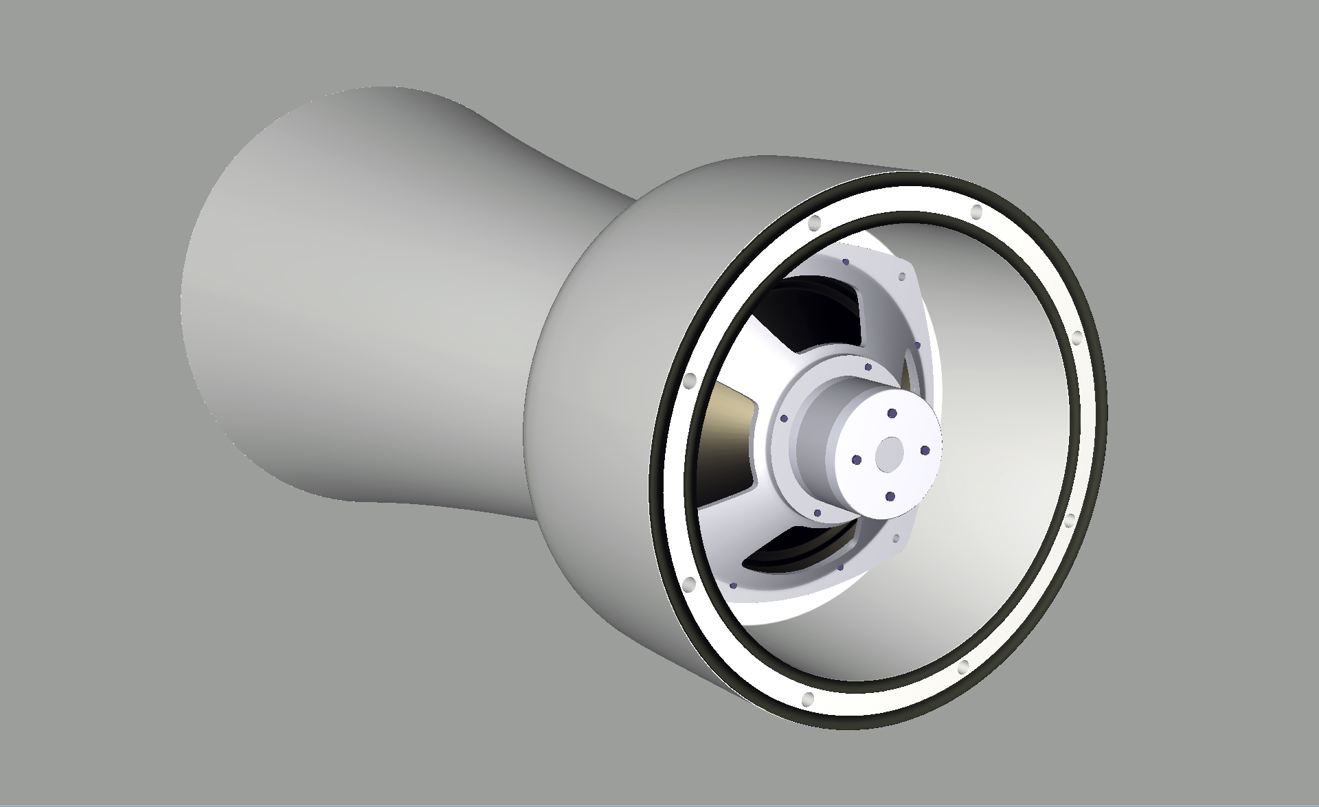
Above : View into rear chamber (45Hz horn /AK151)
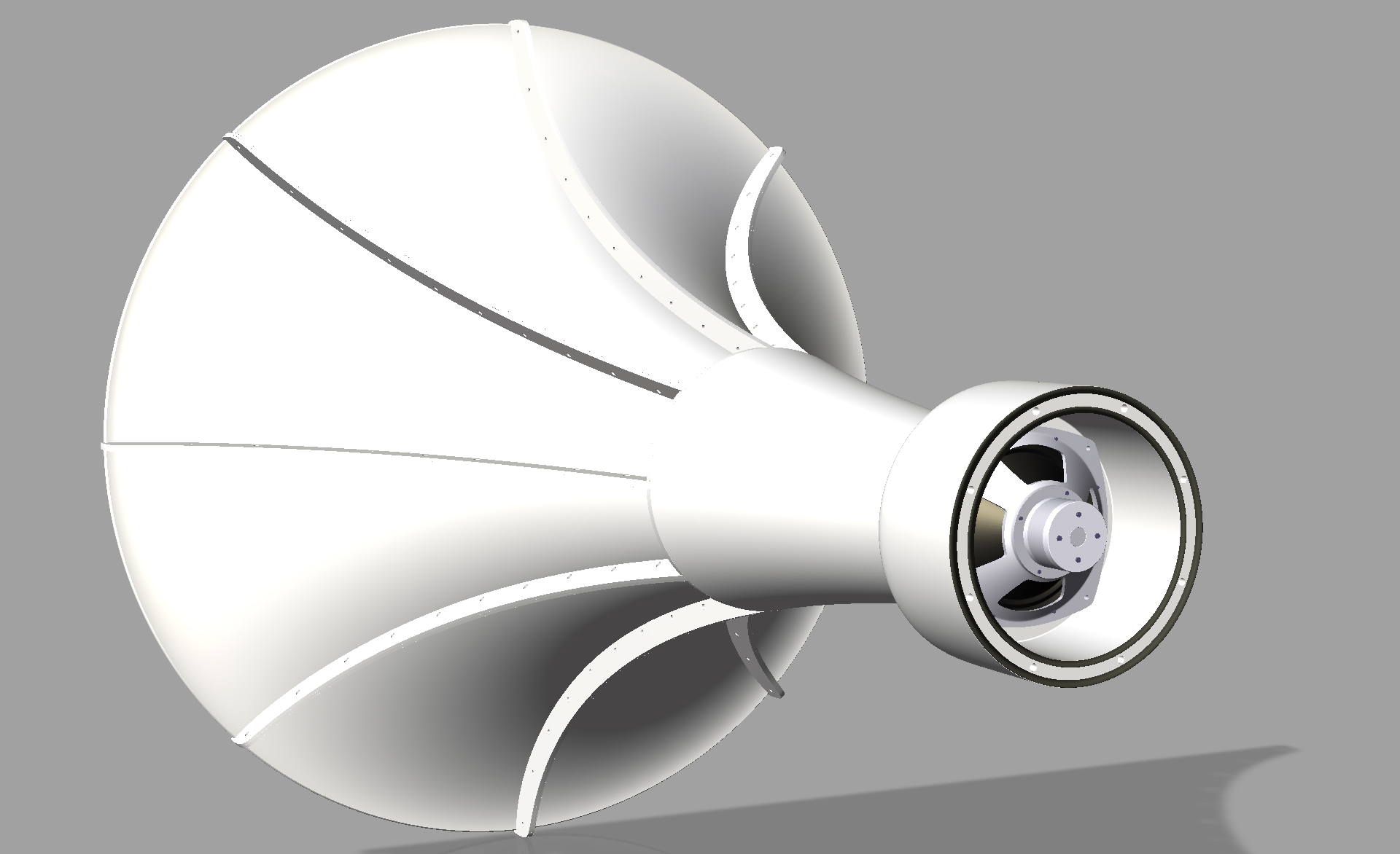
Above : Same but further away
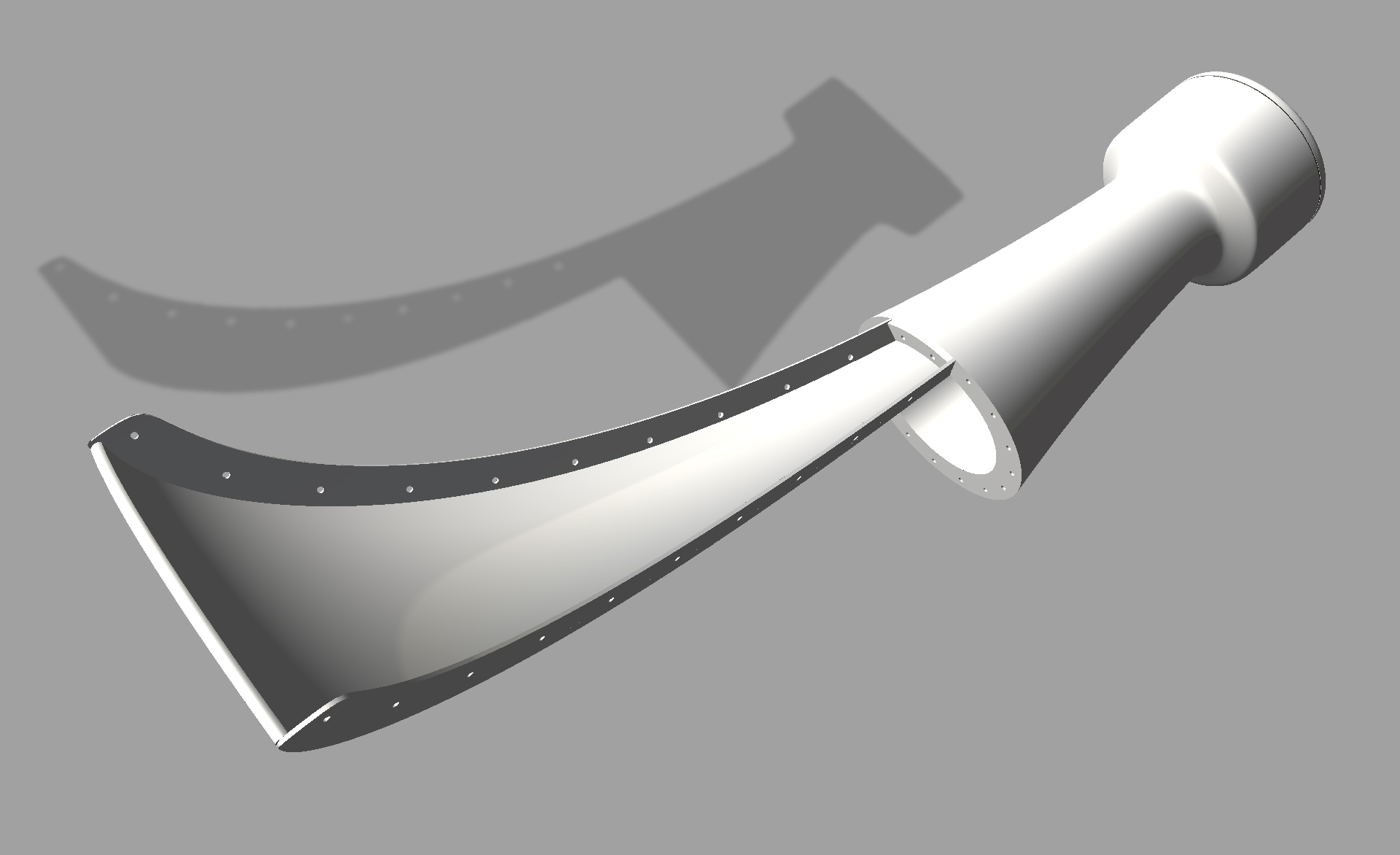
Above : View showing the attachment of one of the segments
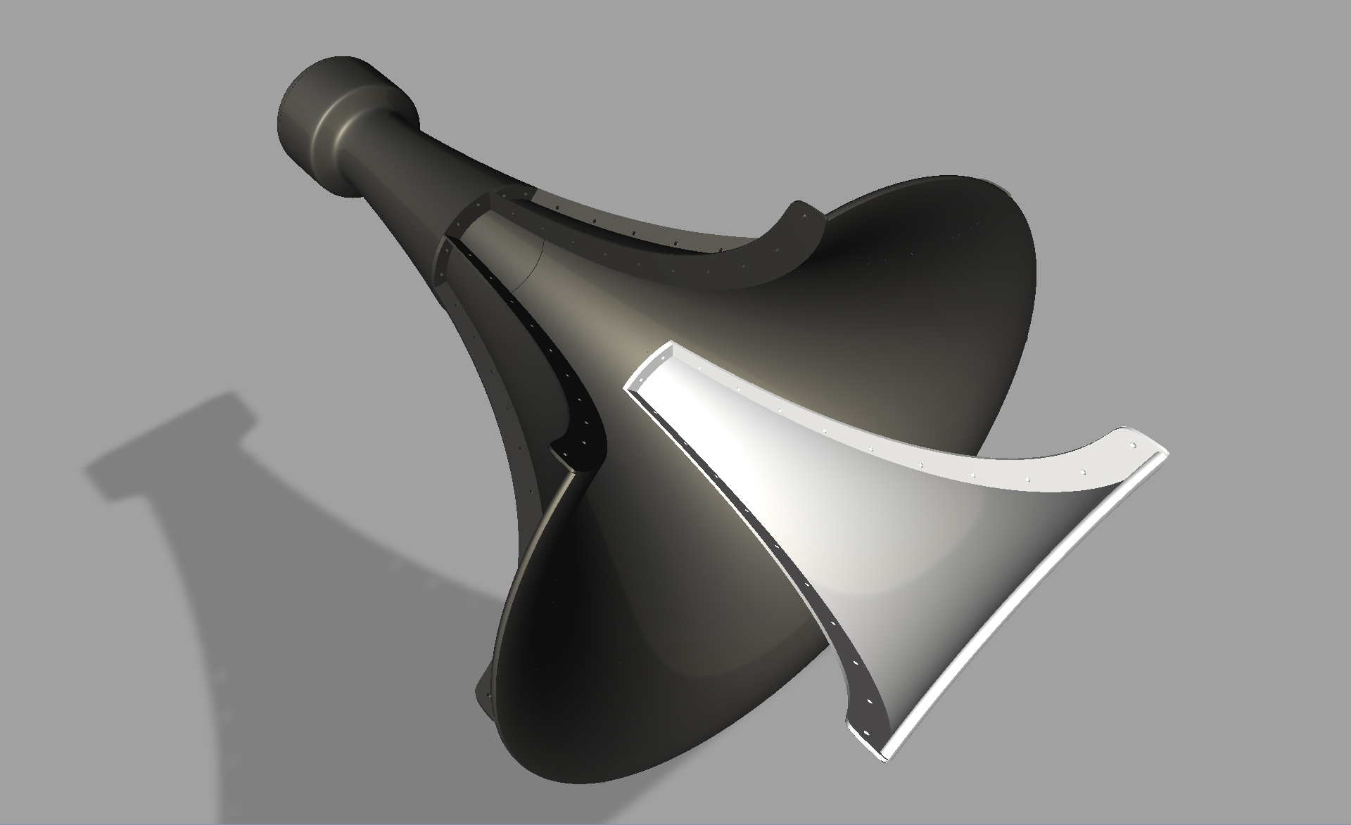
Above : Exploded view
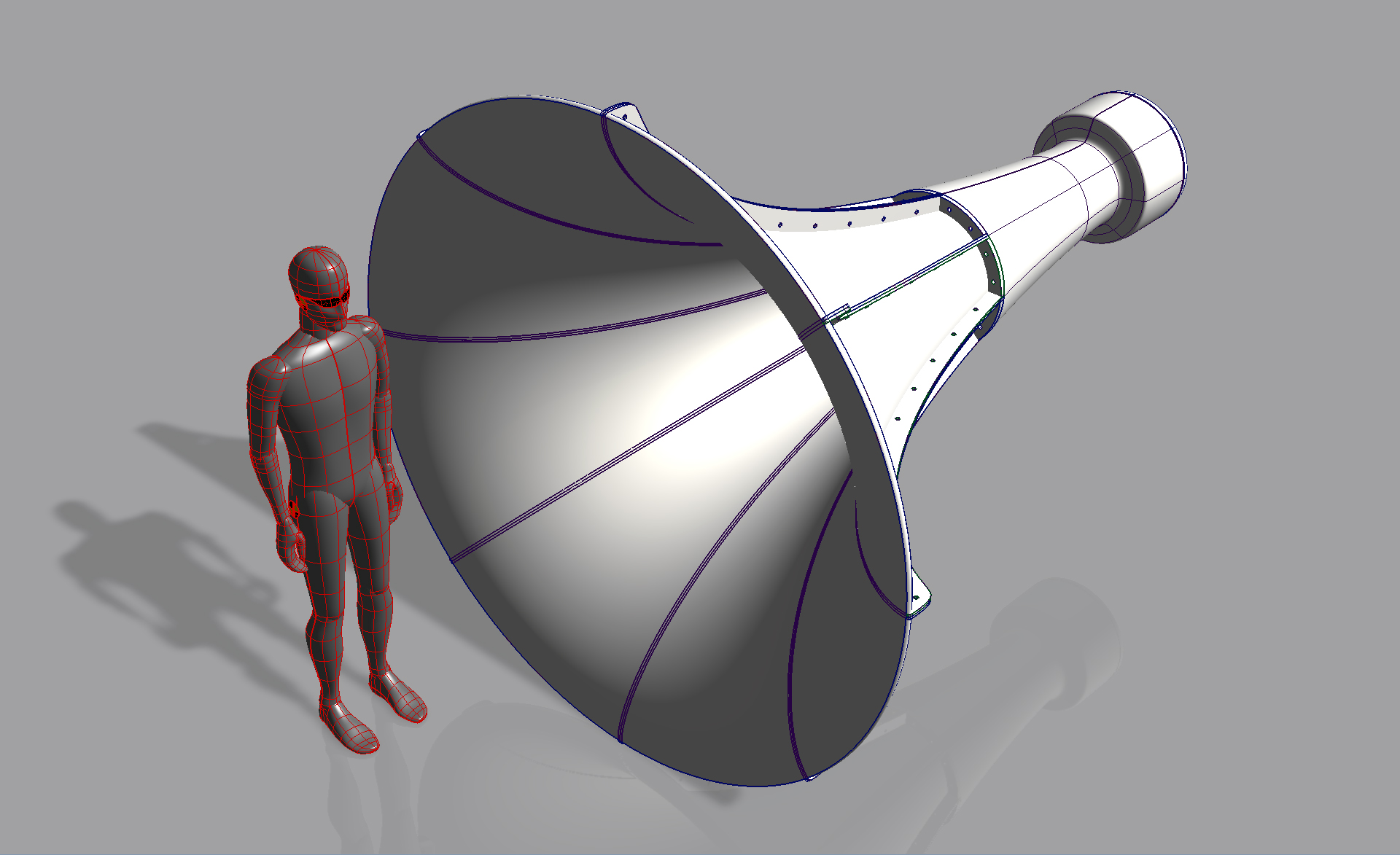
Above : View with 6ft tall figure
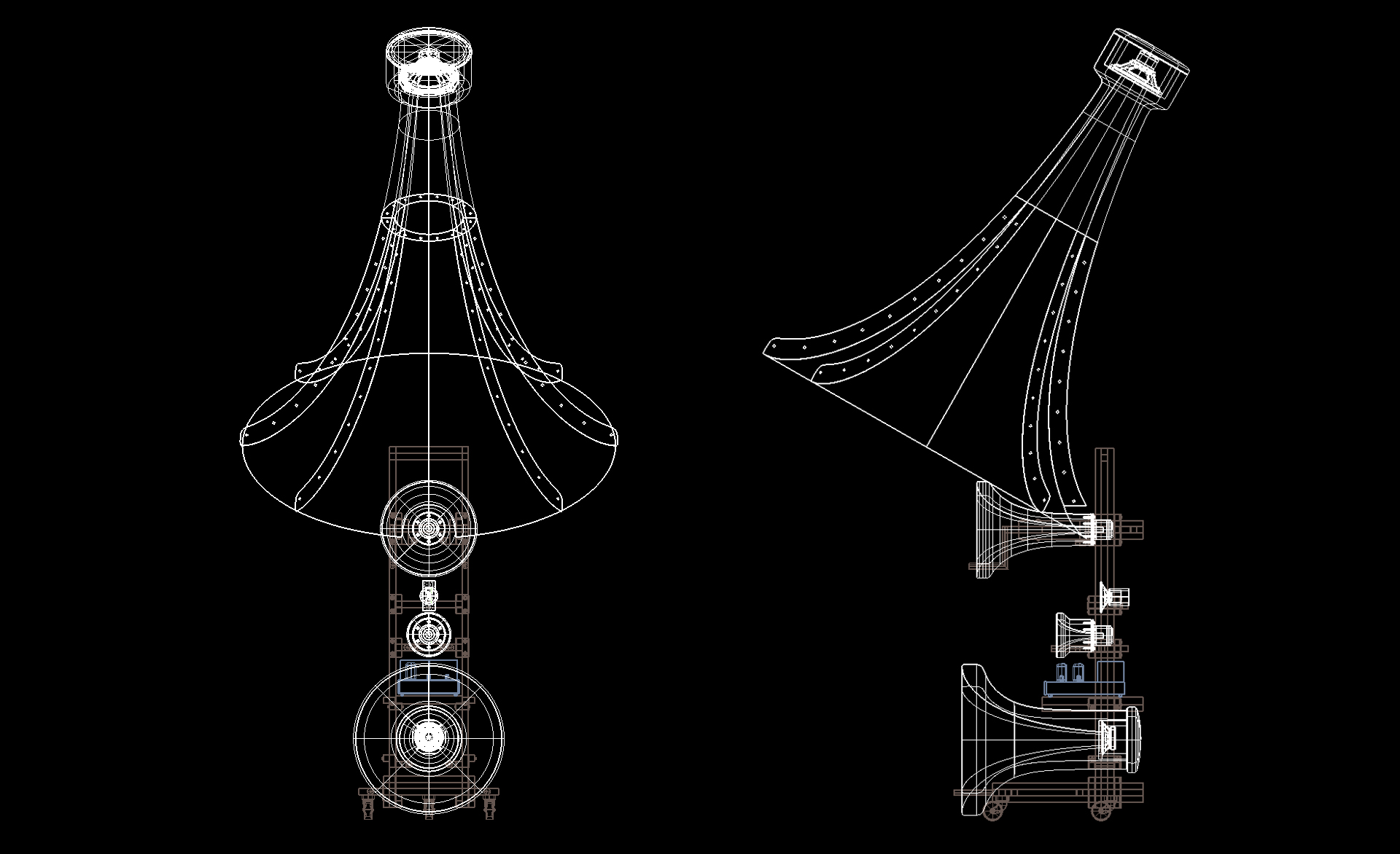
Above : Location relative to of all other horns
|
|
|
|
Posted by Romy the Cat on
08-04-2007
|
|
Jessie, I have moved your post to your 45Hz horns thread but then decided to keep it here as some of my comments would be about entire system not only about your midbass horn. Anyhow, there is nothing there to laugh and it is pleasant to see that some people not only run own mouths but do serious and highly objectionable thanks. Below are some of my raw comments, not organized, without any order; use them at your discretion.
1) You might not need rubber gaskets at back chamber of your mid-bass horn.
2) Make sure that you have as sufficient volume of back chamber; it is simpler to make it smaller after the horn is built than larger. Measure the resonance frequency of your bass driver and to see how much you need to open up the chamber.
3) I feel is that the join it in the back bulge and the body of the bass horn is slightly weak. I would make a line from back chamber to the horn thicker; in fact I would run the entire back section of the midbass horn as a cylinder instead as an exponential profile.
4) The segments of the midbass horn, what the material will be might from? It looks like metal, would it be? It is very hard to estimate how sufficient the sickness of this mental and amount of the ribs will be necessary, as well as the amount of colorations that might or might not take place would be hardly quantifiable. However, what I would do if I undertake this type of project, would be an production in initial design of the midbass horn a mechanism that would allow me to deal with typical mouths resonance later. It might be a system of straps, or a system of fasteners that would allow need to lay down the heavy-rubber panels in the valleys along the segments and to squeezes them to the body of the horn. I was thinking about something along those lines.
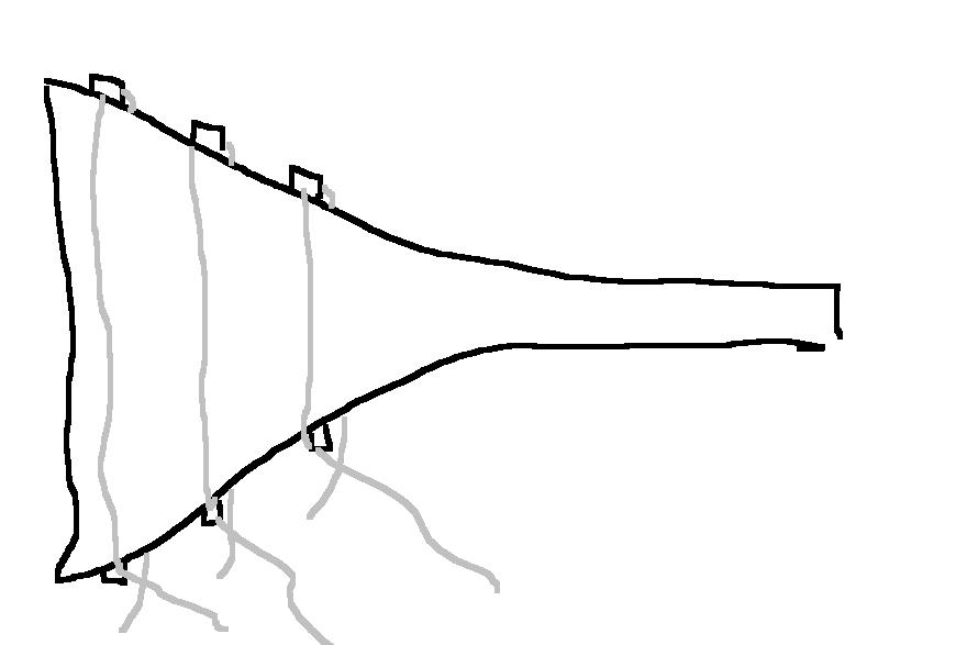
It would not be difficult to implement to begin with but it would be very-very useful if you eventually decided to mass-load the mouth or damp it.
5) I live like your frame where his ability to adjust the height of the top lower-midrange horn. That would allow you to play very liberally with different tweeters and different crossover points at lower midrange horn.
6) Make sure that the whiles on your frame are very small and upper bass horn sits as low as possible, in fact is the way you indenter it down I think is absolutely perfect.
7) Are you planning to locate amplification layer between upper bass horn and midrange horn? It is a good idea but I will suggest making this amplification to be with remote power supply where power transformers will sitting at a separate chassis on the floor. By the way, if you have problem with heat at your amplification layer that you can put amplification behind the frame where midrange driver sits.
8) Did you consider extending the height of your frame all the way up and attaching the large midbass horn on the same vertical pole? If to mound the mid-bass horn at the center of its mass is then it will not be a big burden to the frame. Sure it will create a hell of a selling yacht, and might be too dangerous to experiment with.
9) Be advised that the given design will have difficulties to sound correct in near field position if you are staying as the output of a lower midrange horn would be too prevailing.
10) I know, it's might be too crazy but from where I am staying now I would put into the design the ability to employ an “Injection Channel” (depends what kind of horn drivers your will chose to use)
11) Make sure that you are lower midrange horn has an ability to be extended forward for a few centimeters.
12) Did you think already about the selection of the drivers and crossover points?
13) I would suggest making the arms which are attached to the frame to hold each layer removable from the frame. This way if you decided to use other horn or other drivers then the channel might be completely swappable.
14) With is as certain of liberty of thinking, which would include the selection of the drivers and to the aim of using the Injection Channel I might says that the lower midrange channel (top horn) might not necessary to be used. I have no final opinion on the subject
15) Where in your design would be the “default” targeted vertical listening position of ears (the location where a measuring microphone will be placed)? Is it that top of upper bass horn? The center of midrange horn? The top of midrange horn?
16) Move the back wheels of the frame all the way back.
It was all that in my mind as now. Generally what you are trying to do is from my perspective is wonderful and very noble direction to go and it is what I would do if I would do it. What you are targeting is a next level after Macondo and Cressaro Gamma and if you will be able to implement it properly then you certainly should charge money for people to listen it and to learn “how it might sound”. With a proper selection of the drivers, without proper assessment of the each driver capacity and proper none-intrusive Do-Not-Harm-Crossovering™ will be superbly important. Please keep posting your progress at as it is amazingly fascinating and educational to see what you are doing. Rgs, Romy the caT
|
|
|
|
Posted by Ronnie on
08-04-2007
|
jd: Looks very ..cool! I can't wait to see some more photos!
Romy wrote:
"1) You might not need rubber gaskets at back chamber of your mid-bass horn. "
-I was thinking the same. But perhaps rubber rings can be used to seal the back chamber to make it instantly tune-able (without the hard foam):
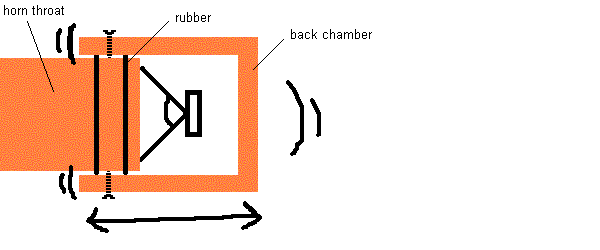
(I haven't tried the idea. The outside surface of my horns is not that even):
|
|
|
|
Posted by Paul S on
08-04-2007
|
Pretty freaking cool, Jessie. So, where can you put this monster where you can still get far enough away to listen to it?!?
If you pursue this, you might tack weld or screw on expanded metal mesh between the ribs of that behemoth so you could use something fairly easy to work with to construct the horn segments/acoustic profile and then layer on deadening material after the thing was +/- situated. I have had good results with acrylic modified cement, but it has not been proven with that sort of power at those frequencies. Parctically speaking, however, it is something you could build up over time until you were happy with it' and it can with care (and practice) be trowelled smooth and/or other fiish materials, such as plaster, can be applied on top for cosmetic effect.
Best regards,
Paul S
|
|
|
|
Posted by guy sergeant on
08-04-2007
|
|
It looks promising JD. What ratio of diaphragm area to throat area did you arrive at (for the large horn) & how did you choose it?
|
|
|
|
Posted by jessie.dazzle on
08-05-2007
|
Thanks Romy, Paul, and Ronnie for the comments and encouragement :
Here are some responses :
1) Rubber gaskets :
Maybe it is not so important to have an “air-tight” seal (???). The rubber gaskets are there to seal the cover to the rear chamber. Ronnie, that’s a really great idea, it would however require machined parts.
2) Rear chamber volume :
The idea is to start with a rear chamber that is tuned for 35-40Hz (so larger than I may need) I could then reduce the volume to tune the chamber for higher frequencies. The chamber in the CAD model corresponds to the quoted Fs of the driver. (40Hz)... However, I need to verify this Fs specification by measurement, as the AK151 is a pre-T/S driver, and I seem to remember that the Fs quoted were estimated.
3) Strength of small end of Mid-Bass :
Yes I would agree... It would be easier to make if it were more cylindrical... However, I am trying to keep the weight for this part under 400 lbs.
I use a lot of long hemp fiber mixed in with hard modeling plaster, which I dose for maximum of strength, meaning I mix it very hard. I have had to destroy some failed attempts, and it requires use of heavy sledgehammer. I have a couple images showing this construction technique (180Hz horn) which I will send in a separate post (looks like this site now makes it possible to include images via the Mac browser... If I am not successful I will post them from a PC sometime during the week)
4) Material & construction options for the large end of the Mid-Bass horn :
Yes at one point my design was similar to what Romy suggests, but in my thoughts the tensioning straps served more as general structural members... I need to think about it with resonance-tuning in mind.
The material for the segments is still not completely decided... Current options are as follows :
A) Laser-cut steel ribs with expanded metal or mesh (exactly as Paul suggested), followed by a laminate of synthetic plaster and woven fabric (this synthetic plaster is the stuff the dentists use).
Pros : Can do it myself Cons : Heavy
B) A laminate of wood in 1/8th inch thick veneer sandwiching cork sheet. Ribs would be cut from thick wood. This would impose a design that is not round but octagonal. It would require the making of a forming tool (no big deal).
Pros : Can do it myself Cons : Octagonal horn section
C) Give the CAD data to my friend who has a prototype fabrication company, and pay for a milled mould so that he can then make the segments from a composite lamination of fiberglass+epoxy resin. I could also have the small end of the horn made by the same people (this approach would theoretically allow me make a few more 45Hz horns if anyone else wanted a pair).
Pros : Could sit back and wait for delivery Cons : Expensive
5) Frame conception :
Frame is very adjustable. All horns except the Upper-Bass (which has only axial adjustment) are vertically and axially adjustable on sliding blocks. A small modification would allow tilting them down (or up), but for the moment it is not in the plan. The horn supports are independent of the main frame, meaning the horns can be placed in any order desired; different supports can be added later. I will pick up the pre-cut metal for the frames tomorrow (a surprising 88 linear meters).
6) Location of Upper-Bass horn relative to floor :
The Upper-Bass horn is as low as I can get it without touching the floor.
7) Location of power amps :
Yes, the power amps sit within the frame, on their own sliding support between the Upper-Bass and Upper-Mid horns. For the moment I am using a pair of ML2s from 60Hz and above. (below 60Hz I use other amps with a pair of Lower-Bass enclosures). I will use the ML2s to get the horns dialed in... Once satisfied, I will take on the building of dedicated amplification... I was originally thinking 5ch Melqs... But am very much following your single-stage project. In any case, the frames can be adapted to hold dedicated amps.
8) Extension of frame to support 45Hz Mid-Bass horns :
Yes, it would require that the two frames be tied together.... There would also be a need to fix the tops of the extensions to the building. I am still working on this.
9) Potential problems with near-field listening :
I prefer a near-field set up; which is good, because I am forced to use a near-field setup.
When you (Romy) say :
“...the output of a lower midrange horn would be too prevailing”...
Do you mean the output from the 180Hz Lower-Mid will be coming from a point that is too high (or did you mean to say the 45Hz Mid-Bass horn)? Would tilting down the 180Hz horn help this (I understand it would restrict listening to one point)?
To answer Paul’s question :
“...So, where can you put this monster where you can still get far enough away to listen to it?...”
Though I like near-field listening, with the 45Hz horn in the picture, I would probably prefer having a bit more space than is currently the case. However, once the horns are done, for various reasons, I am considering moving... In which case I would find a place with proper space for the horns.
10) Integration of Injection Channel :
The frame provides the space to slide in an Injection Channel. I am however trying to avoid this. I would like to get tone from the drivers in the horns... I have recently received a few pairs of 8-inch drivers... Playing them in free-air, one German-made pair stands out. I have not yet tried them in the horns (the Upper-Bass horns are still not dry), but comparing them in free air to the Fane 8Ms, running full range with an identical signal, they are significantly more sensitive and seem to sound a bit warmer. I will post my findings when the horns are completely dry.
11) Axial adjustability of Lower-Mid horn.
The support has a 35cm range of axial adjustment.
12) Did you think already about the selection of the drivers and crossover points?
Here is what I currently have in place :
High-Frequency : Electrovoice T350 :
From : 16500Hz
To : Open
Upper Mid-Range : Vitavox S2 > 400Hz Tractrix :
From : 3200Hz
To : Open
Lower Mid-Range : Vitavox S2 > 180Hz Tractrix :
From : 790Hz
To : 3200Hz
Upper Bass : Driver still under consideration > 115Hz Tractrix :
From : 240Hz
To : 770Hz
Mid Bass : Vitavox AK151 > 45Hz Tractrix :
From : 60Hz (need parts)
To : 240Hz
Lower Bass : McCauley 6174 in 15 cu ft Sealed :
From : 15Hz
To : 60Hz
Crossovers horns (60Hz and up) : 1st order passive. No attenuation.
14) Replacement of Lower-Mid horn (180Hz) by Injection Channel :
I really appreciate the result of the 180Hz horn with the S2... Particularly in terms of "texture". It is responsible for such an important range... I would not expect this result from a direct radiating driver.
15) “Default” targeted vertical listening position :
It is the center of the Mid-Range horn (the 400Hz horn). This is one reason the Upper-Bass horn is not larger.
16) Location of rear wheel :
Yes moving this wheel further rearward would add a measure of stability. The current location of the rear wheel is based on a design that is made to come apart and fit in the elevator... The rear wheel is mounted to the vertical mast, which is on a (fore and aft) sliding support. What you see behind the vertical mast are the ends of the horizontal base rails. I may have to rethink this.
Once again, thanks for the all the terriffic input.
I will now try to post a couple images...
jd*
|
|
|
|
Posted by jessie.dazzle on
08-05-2007
|
With a bit of luck I will manage to include a coulple images referred to in my previous post :
|
|
|
|
Posted by jessie.dazzle on
08-05-2007
|
Ok, I see how it works... Here is the other image... These images pertain to the subject of the distribution of mass in horns :
|
|
|
|
Posted by jessie.dazzle on
08-05-2007
|
Hello guy,
Regarding your question : "...What ratio of diaphragm area to throat area did you arrive at (for the large horn) & how did you choose it?..."
The ratio I used for the 45Hz horn is about 65% of the ø of the diaphragm LESS THE SUSPENSION.
ø of diaphragm less suspension (AK151) : 11.25 inches
ø throat (45Hz horn in the illustrations) : 7 inches
Ratio : 65%
I arrived at this ratio via the following logic : This is a Bass horn, and it needs to be long to be effective... I will be using it down to about 60Hz ; a 60Hz wave measures about 18 ft long... I targeted a half wavelength dimension at 55Hz. I also looked at other horns which don't simply use the diameter of the driver as a throat diameter (taking info from actual horns in a local audio shop and also from various postings on the web).
If you take Romy's Upper-Bass horn for example :
ø of diaphragm less suspension (Fane 8M) : 6 inches
ø throat : 4 inches
Ratio : 65%
Nothing left to do but try it and hope for the best...
jd*
|
|
|
|
Posted by Romy the Cat on
08-05-2007
|
|
Jessie, I pulled posts from Macondo Axioms thread and encapsulated them onto a new thread dedicated explicitly to your project. I hope you do not mind.
 jessie.dazzle wrote: jessie.dazzle wrote: | This would impose a design that is not round but octagonal. It would require the making of a forming tool (no big deal).
Pros : Can do it myself Cons : Octagonal horn section |
|
I do not think that “not round” will be a problem. For those types of frequencies a small deviation from spherical shape should not affect a lot. Furthermore, do not have round shape will be superbly beneficial for that midbass horn as you will have more ease to hang it. Also, and it is very-very important, the bottom line all the midbass horn will a short straight line instead of a radios. That will enable to lower midbass horn relative the top of the lower midrange driver. If to be too “obnoxious”, then I would even conceder to make a small bite-off at the bottom of the midbass horn in order to bring it even lower. However, if you go for non-spherical shape then I would strongly encourage making non-even amount of segments. So it should not be eight segments but nine or eleven, in order to eliminate any near-parallel surfaces inside the mouth of the horn.
 jessie.dazzle wrote: jessie.dazzle wrote: | | Frame is very adjustable. All horns except the Upper-Bass (which has only axial adjustment) are vertically and axially adjustable on sliding blocks. A small modification would allow tilting them down (or up), but for the moment it is not in the plan. The horn supports are independent of the main frame, meaning the horns can be placed in any order desired; different supports can be added later. |
|
Very Nice! Sort of plug-&-play in a loudspeaker design. Very very very cool!
 jessie.dazzle wrote: jessie.dazzle wrote: | 9) Potential problems with near-field listening :
I prefer a near-field set up; which is good, because I am forced to use a near-field setup.
When you (Romy) say :
“...the output of a lower midrange horn would be too prevailing”...
Do you mean the output from the 180Hz Lower-Mid will be coming from a point that is too high (or did you mean to say the 45Hz Mid-Bass horn)? Would tilting down the 180Hz horn help this (I understand it would restrict listening to one point)? |
|
The point that I was making is that lower midrange horn is sitting, at least in my case, right at the height of my ear. So, when I was blubbering that Macondo can be integrated from as insultingly close distance, I implied sitting position. If to stand up at extreme nearfield position then obviously the lower midrange horn will be shooting right at your face and the total balance of sound will be very incorrect (I low-pass my Fundamentals Channel very shortly). So, you might not be able to stay in front of your speaker at nearfield and to conduct the music :-)
 jessie.dazzle wrote: jessie.dazzle wrote: | 10) Integration of Injection Channel :
The frame provides the space to slide in an Injection Channel. I am however trying to avoid this. I would like to get tone from the drivers in the horns |
|
Hmmmm…. OK. BTW, find among your neighbors someone who has an OK sounding Tannoy Red installation and try to listen it… Try to puck those neighbors who do not do anything with driver, crossovers or enclosures. You might find it educational….
 jessie.dazzle wrote: jessie.dazzle wrote: |
Upper Mid-Range : Vitavox S2 > 400Hz Tractrix :
From : 3200Hz
To : Open
Lower Mid-Range : Vitavox S2 > 180Hz Tractrix :
From : 790Hz
To : 3200Hz
Upper Bass : Driver still under consideration > 115Hz Tractrix :
From : 240Hz
To : 770Hz
Mid Bass : Vitavox AK151 > 45Hz Tractrix :
From : 60Hz (need parts)
To : 240Hz |
|
A few comments. Vitavox S2 in 400Hz horn crossed at 3200Hz will sound acoustically much lover. If it is a new plastic diaphragm then it will run all the way to 1000Hz. Therefore the Lower Mid-Range could be cut shorter then 3200Hz. It was very interesting to experiment with it and move the crossover points up and down, letting both S2 channels to work together in mid range. Also, you did VERY good going for Lower Mid-range not 250Hz (as I did) but 180Hz. It was what I am “non-violently” considering to do as well. If you look at the second page of the following thread:
http://www.goodsoundclub.com/Forums/ShowPost.aspx?PostID=2433
Then you will see that S2 and 250Hz horn do not tolerated anything lower then 600Hz, third order, with throwing “horn boom” as punishment.
The bold section of: http://www.GoodSoundClub.com/TreeItem.aspx?PostID=2784
The driver can handle lower but the horn can not. So, my idea was to do for 170Hz-180Hz horn and drop the crossover point for 500H second order. As you understand with a frame of the fixed height is kind of complicated as it will narrowing the window through which the tweeter might shoot. I still, nonetheless, am considering doing it, perhaps going for exponential profile...
Also, since the tip of your from will me small you might consider also a following arrangement. Sure, you can angle the axis of the big horn more sharply.
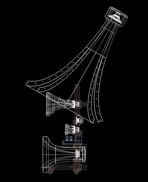
The cat
|
|
|
|
Posted by Paul S on
08-05-2007
|
|
I love not only the beautiful results you are getting, Jessie, but also appreciate that the methods you are adopting allow you to continue to refine your horns on the fly. Particularly nice, to my way of thinking, is that you can tune your horns by adding or removing material, which is hardly a viable option with the more usual choices for construction materials; not to mention the fact that reinforced plaster is DEAD, apart from its surface, which can yet be sealed, shellacked, doped, etc., to taste. It is amazing how little is required +/- to make audible changes. Of course, the horns could be made over a mold, which could be made of foam, for that matter, with the control curve plotted/traced onto a piece of sheet metal or even heavy paper. Both "sides" of the curve plot could be used, one for the mold and one to check/control the profile during interior finishing.
As for the resonant/injection channel, I would recommend a 10" unit with a paper diaphragm. This will be "fast" enough for the use, I would guess, and the 10" just has so much more to offer in the way of "color" in the mids/lower-mids. I happen to use an 8" driver at the heart of my own rig, so I am not selling anything with prejudice. It's just that I am pretty sure you will find a 10" better suited, if you shop and compare, for this application. If you run it with EQ/dedicated amplification, then maybe an old Fulton 100? Might be too low efficiency, but, oh, the palette!
Anyway, thanks for sharing, Jessie. This is as much fun as I've had with someone else's toys in quite a while!
Best regards,
Paul S
|
|
|
|
Posted by Romy the Cat on
08-05-2007
|
 jessie.dazzle wrote: jessie.dazzle wrote: |
7) Location of power amps :
Yes, the power amps sit within the frame, on their own sliding support between the Upper-Bass and Upper-Mid horns. For the moment I am using a pair of ML2s from 60Hz and above. (below 60Hz I use other amps with a pair of Lower-Bass enclosures). I will use the ML2s to get the horns dialed in... Once satisfied, I will take on the building of dedicated amplification... I was originally thinking 5ch Melqs... But am very much following your single-stage project. In any case, the frames can be adapted to hold dedicated amps. |
|
Jessie,
I would like to pass some observations regarding my virtual experiences with location of amplification within the frame of my Macondo. Your acoustic system (by the way you need come up with a name, at least for us to refer to it) will be somehow similar to Macondo and I think you might consider my past examination of this subject.
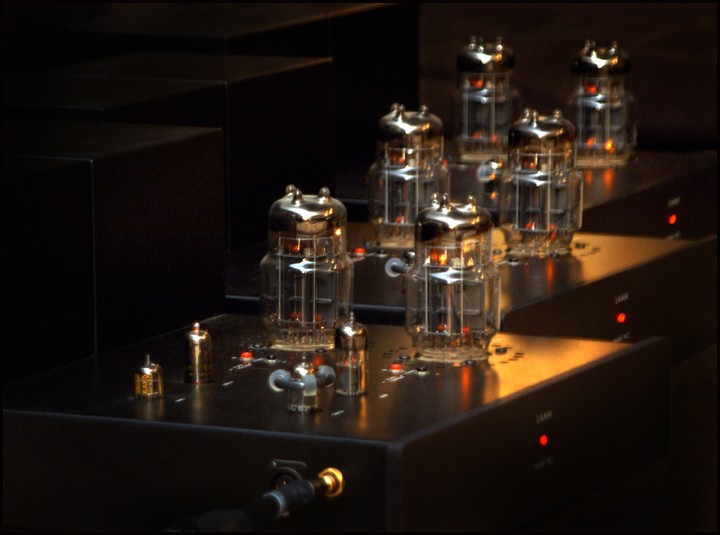
If you go for building off dedicated amplifiers then locate them in frame might make sense, considering that the design olds amplifiers and thier packaging will be made having the idiosyncrasy of the frame in mind. However, I would not recommend to putting Lamm ML2 in the application layer of your speaker, and I would keep Lamm sitting on the floor next to the loudspeaker. ML2 is too large, 88 pounds of rectangular mass, with 2 large tubes which dissipate a lot of heat. I think it is irrational to stick the entire amplifier with its power supplys inside of frame. You would need to make and very strong, very strict, very expensive arm-shelf for that amp, and then to trash the arm-shelf, as when you go for dedicated amplification, as dedicated amplification will acquire completely different arm-shelf. Also, Lamm ML2 is quite sensitive to what it sits upon. You'll have experimented, I'm sure, with various platforms and suspenders for these amplifiers and you will have witnessed is that they does affect the sound of ML2. I presume that the arm-shelf within in your frame will not, or might not, be an optimal surface to care ML2. Whatever this surface will be you will be forced to use it as you will not have space to put anything under ML2 (you will have ~10-11” to play with).
There is another factor, which might the laughable for others, but to me personally it would be a major impediment - I hate to see loudspeakers. I religiously distaste any loudspeakers of the bright colors, any equipment with bright features on it, or any other explicitly creamy features on something which is visible - in most cases the acoustic systems. I paint all my stuff in matte black. The darker, the less informing installation is looking is the better to me. I tend to listen in dark, I tend to close my eyes, and if I open my eyes than I would like to be less distracted with playback appearance. To me personally it would be extremely distracting if I would have two full lit 6C33C seating inside of my loudspeakers, in the open space, right and the level of my eyes. So if I were doing amplification mounting inside of the frame then I would hide the lights from the tube at any cost. By the way, do not forget that Lamm ML2 is not a symmetrical amplifier that will make it slightly ugly looking inside a speaker’s frame for the people who even enjoyed watching the tubes glowing… :-)
Rgs, Romy the Cat
|
|
|
|
Posted by jessie.dazzle on
08-06-2007
|
 Kiom wrote: Kiom wrote: |
great project ! do you have a idea when it will be ready ? |
|
Hello Kiom,
I imagine getting the frames done and all but the 45Hz horns in place by September.
Because of the mass involved, the Upper-Bass horns take FOREVER to dry... This has been further aggravated by the fact that we have had a wonderful month of November this July and first part of August! The horns need to be completely dry before they are safe (and "light" enough) to move.
As for the 45Hz horns... I will know more about completion date once I actually get started on them.
I will post my progress here on Romy's site.
jd*
|
|
|
|
Posted by guy sergeant on
08-06-2007
|
Hi Jessie.
I haven't built anything like the project you are attempting although I have thought about such things. Sadly I don't have the space either! i'd definitely be interested in coming to hear it when its completed & working satisfactorily.
One issue that I would consider is that the Tractrix profile supposedly does not lend itself aswell to extremely low frequency horns (being too short) as other profiles in particular the Hypex (Salmon) shape. I was wondering whether it was actually possible to add an element to the tractrix formula which lengthens the horn expansion in the way that a T value of 0.5 or 0.6 does to a conventional exponential expansion and therefore obtain an LF response that gets closer to the theoretical Horn cut-off frequency than the tractrix expansion might normally allow.
|
|
|
|
Posted by Romy the Cat on
08-06-2007
|
 guy sergeant wrote: guy sergeant wrote: | | One issue that I would consider is that the Tractrix profile supposedly does not lend itself aswell to extremely low frequency horns (being too short) as other profiles in particular the Hypex (Salmon) shape. |
|
Yep, it was very predictable, and after post #1 I was wondering how long it would be before post #15 appeared. It did not take long!
The subject that Guy brought is very complicated, controversial and most likely should upset Jessie as there is not defined answer to it. Let look a slightly deeper into the issue.
There are no doubts in my mind that for MF frequencies no other profiles beside Tractrix must be use (or the negative opening Tractrix – the French one, which is basically is the same). However what we slide down the frequencies then the situation become less one-sided.
When horn touches less than ~300Hz (???) then some people mention some "benefits" of Exponential curve.
This definition of the “benefits” is complicated as I have no definitive judgment on the subject. I personally never was able to conduct the methodologically correct evaluation of the horns, make to be the same rate but featuring Tractrix and Exponential curves. All Exponential horns that I had/heard were serial production rectangular horns, with the typical metal harmonics problems and all Tractrix were custom spherical. Even if I had the same Tractrix and Exponential horn then to make a correct listening assessment is not so simple. The Exponential horn allows itself to be crossed closer to the horn’s cut off, that would make Tractrix and Exponential of the same rate to sound different. Sure, it is possible to cross the identical Tractrix and Exponential, identically imbed them into room and see what happen but I did not do this personally and I do not know anyone who did. I am slowly contemplating, if it worth to pay another $1.5K for a new 250Hz Exponential for my Fundamental Channel to research this subject as I am not completely satisfied with hat my current 250Hz Tractrix does. If some one has 250Hz Round Exponential and can lend it to me for a few weeks it would be wonderful and I would not mind to pay rent.
So, the only people who can shade some light on the subject would be the people who built the horns. Bruce Edgar is unquestionably the most experienced among all and has most qualifications. I consulted with Bruce about it and he feels that Exponential horn of identical rate just has subjectively “more bass”. He however admits that that “more bass” has an idiosyncratic tone in it that does not exist in Tractrix. Here is where the complexity comes…. Do the Exponential horns have “more bass” because they allow to be loaded deeper? Will the Exponential horns offer “more bass” if the bass cut off point will judged not by amplitude but by the “bass cleanliness” that we hear via Tractrix? What is the value of that “idiosyncratic tone of the Exponential horns” and is it possible to USE it beneficially? I personally can advocate the answers to those questions from both sides… and the “right” answer will be only on context of a specific attempt and the specific results.
Now, let look at the Jessie project from the perspective of Tractrix vs. Exponential debate.
The Upper Mid-Range 400Hz Tractrix – that is no question that nothing besides Tractrix must be used.
The Lower Mid-Range 180Hz Tractrix – that might be exponential candidate to get more bass out of S2 lower knee, particularly if Jessie will drop the S2 primary resonance. However, we do not know (and Jessie do not know) where he will low-pass his Lower Mid-Range channel. If it were around 1000Hz (as I do) then the Exponential might be considered, if it will be higher (and there is rational to do it as well) then I would stay with Tractrix. Still, even if Jessie stays with lower low-pass and go Exponential then what will be sound of S2 in that setting? We do know that S2 does in 220H Exponential made by Vitavox, crossed at 500Hz, second order. The Lower knew of that setting is very good. Is it “clean”? Not really. Take that Vitavox-made 220H Exponential and try to talk into it. You will see it has heavy nasal colorations… To cure those nasal colorations the horn should be high-passed heavier… Will this high-passing kill all the “bass benefits” of the Exponential curve? I do not know the answer.
The Upper Bass 115Hz Tractrix. That is another candidate to employ the Exponential “thump” but let look deeper. In the Jessie’s case the Upper Bass will be the only properly implemented Upper Bass that I ever seen. No one, including me, can afford to have 115Hz Tractrix and to cross it at 240Hz. All our horns are fundamentally compromised because we are trying to push more bass out of our horn running them the last “octave down”. Jessie has no need to push the “last drop” from his Upper Bass horn as he has his Mid Bass horns. Well, Jessie’s Upper Bass channel is in a way sonically “unnecessary channel” as his Mid Bass horn can care the Upper Bass Upper signal. What Jessie’s Upper Bass horn does is “anchor” the entire Jessie’s acoustic system. The upper region of Jessie’s Upper Bass channels is directional and if it will be radiate ONLY from horn hangings from the roof then the system (particularly combined with the output of the relatively high-located Lower Mid-Range channel) will have horrible imaging. So, what Upper Bass does, is creates a virtual array of the drivers, lowering the centering radiation point to the ears level. When Jessie’s will finish his horns and will be playing with fine-tuning and integration of channels then turning off the HF and MF channels and playing with high-pass of his Upper Bass horn he will be able to center the vertical image of the system right where the MF will be. Therefore, in context of the Jessie’s system I do not see a lot of need for Upper Bass to have more “Exponential Bass”. Ah, did I mention that Jessie’s Upper Bass Tractrix is ~8 shorter then the Exponential would be?
The Mid Bass 45Hz Tractrix. This is the only candidate that I see in Jessie’s future installation that might be worth to consider to go Exponential as he would need push this horn at it’s bass’s maximum. Unfortunately no one will tell him the right answer in turn of Sound. If I were Jessie and was in front of the decision to make I would probably bother any horn-maker in the World, getting their opinions, getting second, third, fifth, twenty seventh opinions… I would model the competition between Tractrix and Exponential at I would say 300Hz and to see how it works. No one knows anything…. The Exponential will have “more bass” but how right that bass will be?
OK, now somebody will hate me…
As the absolute crazy but the absolutely noblest idea, and considering that it will be LF horn, also considering Jessie experience with molding plasters, I would propose following: figure out the delta between Exponential and Tractrix curve and make the big horn …. in conical shape, I would say 11 straight segments. It will be cheap to do in metal, aluminum for instance. Then inside the belly of the horn (to the each segment) make a detachable insert that will convert the profile of the horn into Exponential, Tractrix or any other imaginable curve. The interesting part is that the plaster insert might be a perfect damper for the frame of the bass horn… Rgs, Romy the Cat
|
|
|
|
Posted by jessie.dazzle on
08-06-2007
|
 Romy the Cat wrote: Romy the Cat wrote: | |
"...Jessie, I pulled posts from Macondo Axioms thread and encapsulated them onto a new thread dedicated explicitly to your project. I hope you do not mind..."
No problem... I was actually starting to feel a bit apprehensive about going "off thread" in the original location.
I just noticed that there is a slight error in the word "Project" (you wrote "Peoject").
"...Also, and it is very-very important, the bottom line all the midbass horn will a short straight line instead of a radios. That will enable to lower midbass horn relative the top of the lower midrange driver. If to be too “obnoxious”, then I would even conceder to make a small bite-off at the bottom of the midbass horn in order to bring it even lower..."
If you look closely at the images, the "bite" was in fact taken out of the mouth of the horn.
"...However, if you go for non-spherical shape then I would strongly encourage making non-even amount of segments. So it should not be eight segments but nine or eleven, in order to eliminate any near-parallel surfaces inside the mouth of the horn..."
Very good point! (easy to accommodate)
"...The point that I was making is that lower midrange horn is sitting, at least in my case, right at the height of my ear. So, when I was blubbering that Macondo can be integrated from as insultingly close distance, I implied sitting position. If to stand up at extreme nearfield position then obviously the lower midrange horn will be shooting right at your face and the total balance of sound will be very incorrect (I low-pass my Fundamentals Channel very shortly). So, you might not be able to stay in front of your speaker at nearfield and to conduct the music :-)..."
Ahh.... Ok. So I'll have to dig a pit in the floor.
"...BTW, find among your neighbors someone who has an OK sounding Tannoy Red installation and try to listen it… Try to puck those neighbors who do not do anything with driver, crossovers or enclosures. You might find it educational..."
If you could meet my neighbors, you would find even more humor in the above suggestion... I will keep my eyes open for a pair to buy... No risk as it is easy to resell them.
"...A few comments. Vitavox S2 in 400Hz horn crossed at 3200Hz will sound acoustically much lover. If it is a new plastic diaphragm then it will run all the way to 1000Hz. Therefore the Lower Mid-Range could be cut shorter then 3200Hz. It was very interesting to experiment with it and move the crossover points up and down, letting both S2 channels to work together in mid range..."
Once the frames are in place with the horns I will get the mic and the RTA out and get more serious about setting up the crossovers. I like the idea of letting the 180Hz horn take on a bit more of the work... Its just a question of discovering at what point to hand off the job to the more qualified horn, while avoiding acoustic redundancy.
"...Also, you did VERY good going for Lower Mid-range not 250Hz (as I did) but 180Hz. It was what I am “non-violently” considering to do as well..."
Yes, when interested I remember close to 100% of what I read... So you should really say that I did very well in retaining what I read in your posts before making the decision... It is largely from your experimentation that I drew my conclusion.
"...The driver can handle lower but the horn can not. So, my idea was to do for 170Hz-180Hz horn and drop the crossover point for 500H second order..."
With the 170-180Hz horn why not use 1st order at a higher cut off frequency ?
"...As you understand with a frame of the fixed height is kind of complicated as it will narrowing the window through which the tweeter might shoot. I still, nonetheless, am considering doing it, perhaps going for exponential profile..."
Here is an opportunity to make your frame telescopically adjustable :
Cut off your vertical mast at 3/4 of the way up from the base, then buy 2x1m of square section tube that just fits inside your vertical mast (if you ave trouble finding the correct size, you may have better luck using 4 smaller tubes welded as one)... Get your welder guy to weld one meter of this smaller tube to the vertical part of each of the top 1/4s of your original frames... Also have him drill 3 holes (of a diameter that will accept a large bolt) one in the back, and one on each side of each vertical mast about 5" below the cut, then weld on a big nut centered over each hole... run the bolts in a few threads and insert the top 1/4 (depending on your ceiling, you may have to tilt the frame on its side)... Set the height as desired, and lock all bolts on your new telescopically adjustable frame... Done.
BTW : Today at lunch time I picked up the metal for my frames... The design requires a total of 182 cuts... Even with the super saw this place has, it took one man all of Friday to measure and cut everything... I don't even want to think how long it would have taken me to do it by hand. It is designed so that welding it should be very easy, with minimum possibility for error.
"...Also, since the tip of your from will me small you might consider also a following arrangement. Sure, you can angle the axis of the big horn more sharply..."

I have to think about this idea of stuffing the top of the tower up into the mouth... It could help with "packaging"
"...I would like to pass some observations regarding my virtual experiences with location of amplification within the frame of my Macondo. Your acoustic system (by the way you need come up with a name, at least for us to refer to it) will be somehow similar to Macondo and I think you might consider my past examination of this subject.
About the name... Ok, but I need a few more days to learn the Bantu lingo...
If you go for building off dedicated amplifiers then locate them in frame might make sense, considering that the design olds amplifiers and thier packaging will be made having the idiosyncrasy of the frame in mind. However, I would not recommend to putting Lamm ML2 in the application layer of your speaker, and I would keep Lamm sitting on the floor next to the loudspeaker. ML2 is too large, 88 pounds of rectangular mass, with 2 large tubes which dissipate a lot of heat. I think it is irrational to stick the entire amplifier with its power supplys inside of frame. You would need to make and very strong, very strict, very expensive arm-shelf for that amp, and then to trash the arm-shelf, as when you go for dedicated amplification, as dedicated amplification will acquire completely different arm-shelf.
Well there is no problem for the strength of the arm, but the ML2 may not be the right amp to place there. With regard to the heat issue : Were you refering to degradation of listener comfort, or would warming the horn/driver possibly become an issue?
Also, Lamm ML2 is quite sensitive to what it sits upon. You'll have experimented, I'm sure, with various platforms and suspenders for these amplifiers and you will have witnessed is that they does affect the sound of ML2. I presume that the arm-shelf within in your frame will not, or might not, be an optimal surface to care ML2. Whatever this surface will be you will be forced to use it as you will not have space to put anything under ML2 (you will have ~10-11” to play with).
I currently have the amps sitting on a double layer of... WALKER POINTS!!!... Ha... Just kidding (this is a reference back to the golden days of "verybigamp")... Really, they are sitting on 50mm thick blocks of... laminated hard wood, which in turn are sitting on... are you sitting down?.... 5 blue racket balls (or squash balls), which in turn are held in place by big cast iron pipe flanges which you can find at Home Depot.... the entire platform floats... I mean really FLOATS (I will take a photo some time).
There is another factor, which might the laughable for others, but to me personally it would be a major impediment - I hate to see loudspeakers. I religiously distaste any loudspeakers of the bright colors, any equipment with bright features on it, or any other explicitly creamy features on something which is visible - in most cases the acoustic systems. I paint all my stuff in matte black. The darker, the less informing installation is looking is the better to me. I tend to listen in dark, I tend to close my eyes, and if I open my eyes than I would like to be less distracted with playback appearance.
I agree 100%... But there is political pressure... I will probably have to listen to the W in WAF who has asked for a light finish (after all, she is letting me get away with quite a lot)...
All that aside : In my testing, what gives the best sonic results so far is sealing the horn with polyester resin, then applying several generous coats of bees wax to the inner surface... It ends up looking a bit like pale colored unpolished marble... The resin could of course be tinted whatever color simply by adding pigment... I got to this point by trying one of my moulds with a compression driver (I use the resin and wax to prepare the mould)... I then took it further. I may find something that works better, as I have not tried that many different surface treatments.
To me personally it would be extremely distracting if I would have two full lit 6C33C seating inside of my loudspeakers, in the open space, right and the level of my eyes. So if I were doing amplification mounting inside of the frame then I would hide the lights from the tube at any cost. By the way, do not forget that Lamm ML2 is not a symmetrical amplifier that will make it slightly ugly looking inside a speaker’s frame for the people who even enjoyed watching the tubes glowing… :-)..."
Well again, I don't know if I will really put the ML2s in the frame... Nevertheless, in the seated position (is in the black and white line print above) the tubes would be obscured by the mouth of the Upper-Bass horn.
Thanks again for all the input.
jd* |
|
|
|
|
|
Posted by jessie.dazzle on
08-06-2007
|
Paul,
Thanks for the compliments.
You are exactly correct with regard to how I use a plotted curve and a sheet metal template... The part I like least is cutting out the metal template... This is because I use fairly heavy metal. Which is necessitated by the fact that I use the template to cut the plaster before it sets up, either by rotating the template around a pivot, or by rotating the horn or mould on a table with a fixed vertical pivot (rigidity is the key).
As for injecting the setup, I will keep my eyes open for tone-rich 10-inchers... I also picked up a really nice little pair of alnico 5-inchers that look about ideal to stuff into a horn... I'm curious to give it a try as a kind of mid-range injection, but that experiment will have to wait.
jd*
|
|
|
|
Posted by Romy the Cat on
08-06-2007
|
|
I would like to point out something that is going on here that I found truly remarkable.
For advanced people ho play with horns there is no second opinion that the vertical array, the Macondo/Cressaro-Gamma type of architecture, is THE ONLY one that works well. So, let look what Jessie offered in his design?
He offered a concept of a generic frame to which the custom channels-insets (arm-boards) might be attached. I think it a remarkable solution, the one that open a Pandora box for much wider thinking as I think there is a great business opportunity in what Jessie proposed for someone who have interest in it.
Let pretend that some kind of company take the Jessie’s idea under the wing and begin to commercialize it. They design unified base + vertical monopod with a system of rack and pinions, along with an array of arm-boards attachments, which would have freedom in vertical and horizontal plane (like the positioning tables in milling machine). They market the frame as a base product for any further speaker design. That frame itself might be sold for little money and then the charges might be bubble up for arm-boards or vice versa – it is not important. To build that well-designed frame and arm-boards in today’s mass production would be very-very simple and very inexpensive.
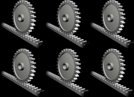
So, the prospective users might load the arm-boards with any horns, any drivers, any box enclosures, ported, sealed, move them up or down, add and remove channels, add single drivers, open baffles, combinations, do upgrades and add amplifiers on the arm-boards… So, the frame become juts a motherboard, to which anything today audio produces might be connected. The concept of having the easy swappable and easily available components addable to a mainframe would appeal to many people and will encourage them to built acoustic system as the people did in 50s, configuring what they can afford and what they can fit in their rooms.
I really think that someone who is willing to be in the business should look at the Jessie’s idea of frame-motherboard and take it further. The best part is that the people who would manufacture such a thing that they would not be engaged in the idiocy of audio: no bribing reviewers, no applying Vaseline to own ass when they see an editor of audio publication, no addressing of the idiotic frustrations of typical users-audio-morons. It is so none related to audio that even I would do something like this. The people who would produce the frame-motherboard will be engaged in a regular machine shop-type of operation with no needs to humiliate themselves by socializing with audio idiocy. Hey, Jim Smith, if you still look for a sexy project, then you'll my look at this deeper.
I believe there is an a lot of a rational behind the concept of frame-motherboard as the audio-victims sick to pay $60,000 for a nicely made pieces of unnecessary furniture featuring two $180-worth drivers. If you can read what I did not say than you'll my found this idea worth to consider. It might be very much “new” in what the today’s audio is Rgs, Romy the Cat
|
|
|
|
Posted by Paul S on
08-06-2007
|
Plasma
Cuts what-you-will like nothin', clean as a whistle, and the system is portable (ie, the Mountain can come to Mohammed).
Also, I see an interior mold and making the inside of the Big Guns' metal a little oversized, to allow the use of the mold, from which you would initially "stand off" your actual finish profile about 1/4" or so, so you could come back and coat/tune the inside of the thing after the outside had set up enough to remove the mold, move it around, work on it with impunity. You could use some funky iteration of machinist's dye (house paint?) as you home in on the originally-intended interior profile. 'Don't suppose you'll be "turning" that Bad Boy!
Best regards,
Paul S
|
|
|
|
Posted by jessie.dazzle on
08-06-2007
|
Guy, I too have had this question (Tractrix vs. Exponential vs. Hypex), and you are right to bring it up.
I very much appreciated Romy's comments on the subject... Including the modular horn with interchangeable profiles proposal... (It might be time to ease up on those Cohibas!)... Actually the idea has me thinking of alternative construction methods...
To be completely honest here, I have not completely decided... In fact my original notes specify a Hypex profile.
I have the (non Excel-based) software to quickly create the numbers for tractrix profiles, so just used that to develop the rough CAD model as a sort of place holder.
As mentioned, I plan to run the 45 Hz horns down to 60Hz, which is lower than I would like to push them.
The sub 60Hz range is well covered by a pair of Lower-Bass enclosures... I am very pleased with their performance. They can handle running a bit higher... Say to 80Hz, but (for more than one reason) I would rather not ask this of them.
I need to think more about it.
jd*
|
|