|
Posted by Romy the Cat on
04-01-2007
|
|
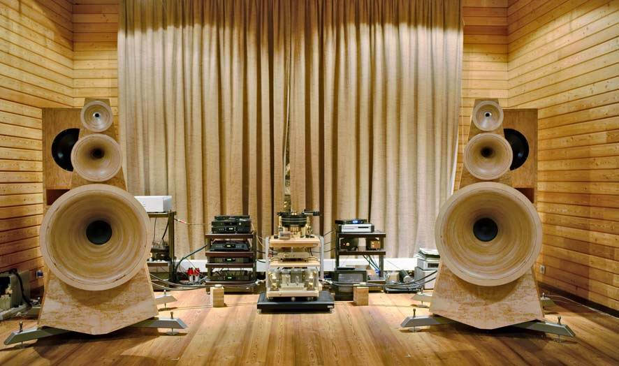
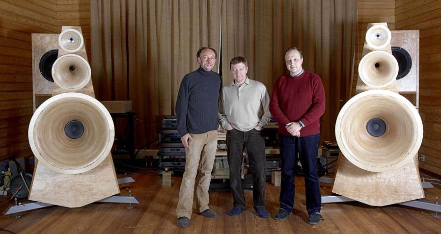
Here another horny “client” – German company “Odeon”
http://www.odeon-audio.com/ Look at those miserable Germans: the Avantgarde, Cessaro and Odeon! Wow, and it is from a country the size of New Jersey… :-)
Of course I am kidding… Dose anyone know what drivers they use? Sure, there is a LOT of wrong with those horn but still people are trying something, poorly but still trying…
Anyhow here are some images of the Odeon systems:
|
|
|
|
Posted by drdna on
04-01-2007
|
 Romy the Cat wrote: Romy the Cat wrote: | | Sure, there is a LOT of wrong with those horn but still people are trying something, poorly but still trying… |
|
You say there is a lot wrong here, but the fundamental setup is actually rather similar to the Macondos it seems in terms of the idea of how the frequencies were divided up, roughly speaking. The horns are not positioned optimally vertically, they don't seem to be time-aligned correctly, and the lathe-work is rough on some of the horns. WHat are your other observations, Romy, just for my own education?
Adrian
|
|
|
|
Posted by Romy the Cat on
04-02-2007
|
Adrian,
You pretty much said it but do not think that what you said it minor – it is in fact huge, with exception of some rough lathe-work: it is not exactly true but if it was true then it would be irrelevant to Sound.
I really do not know what was in the head of the Odeon guys when they did what they did.
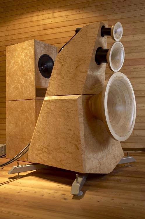
1) Vertical positioning: it is absolutely strange. A conventional height of listener ears is 40”-44” It is the height of Odeon upperbass axis. Why they did it I have no idea. The Odeon upperbass looks like 150Hz and the next channel looks like 350Hz. It means that the upperbass works most likely from150Hz to 800Hz. Why they need to shot this region from the level of the listener ears? Only God knows. They have an empirical center of the MF channels at 6 feet!!! Are they crazy or they are planning to listen the thing from no closer then 20 feet?
2) Very strange bugle at the bottom - juts waste of wood and valuable space. I have a design where I was trying to inject under a mouth of upperbass horn a LF woofer. It was a special type of LF channel that used a special driver, an ultra small enclosure and eated a lot of power (similar to Sunfire True Subwoofer). It does not look that Odeon used the bulge for anything LF-useful. (look #4 for more)
3) Absolutely stupid stand with spikes and so in. It is very much unnecessary and juts waste the coupling of the upperbass horns with Flore – it is where they loose ~10Hz
4) I might presume that Odeon peoples were trying stick into the pyramid of their speaker one more channel – midbass horn that has a driver between MF and upperbass and fires down. The idea never was good as to implement it they need to sacrifice everything – it is what they did bit in retie to get still very compromised midbass
5) The Angled axis – the big red flag - instantaneously
6) Very stupid front mouth termination.
7) Ported bass- it is with dedicated sections of looks like 30-40 cub feet!!!
8) It looks like too shallow upperbass
9) Absolutely barbaric time-alignment. In the horn world this arrangement will sound like absolute crap. Interesting that they with their shallow upperbass do have space to align the MF channels but they intentionally have chosen do not do it.
I can go on and on but it does not look that the Odeon were really serious about what they do. The Odeon are very far from the ideas of Cessaro Gamma and the ideas of Macondo…
The CaT
|
|
|
|
Posted by be on
04-02-2007
|
Actually as far as I can see from the picture and trying to estimate the location of the drivers in the horns: The 3 front horns are probably time aligned, meaning the drivers are lying on an circle with the center at the hight of the listener and the radius same as a certain listening distance.
But maybe I'am wrong, one would need a measuring band to be shure.
Vertical sound localisation happens as far as I know thru a comb filter effect of the ear. The character of the comb filter depends strongly of the the vertical angle of the sound source.
The comb filter characteristic is very complicated and is different for each individuals ears.
So it would be practicaly imposible to make an invers filter to compensate for the angeled listening axsis.
As an experiment I once tried a similar set up, regardin the listening axis.
The sound was dysfunctional in a way I have never experienced before, it gave a simmilar feeling as when one looks thru a lens that inverts the picture and you try to walk around
|
|
|
|
Posted by Romy the Cat on
04-02-2007
|
| be wrote: | | Actually as far as I can see from the picture and trying to estimate the location of the drivers in the horns: The 3 front horns are probably time aligned, meaning the drivers are lying on an circle with the center at the hight of the listener and the radius same as a certain listening distance. But maybe I'am wrong, one would need a measuring band to be shure. |
|
I was thinking about it as well. The obvious lack of compliance with this idea of the upperbass horn might be addressed by this angling of the upperbass axis relative to MF, where the MF is a reference. Angling axis changed timing for a given distance. Yes it is possible for “outside” horns but it is absolutely impractical for channel that is in band-pass.
Anyhow, I do not know what the purpose of that long pipe behind the HF driver, it think it is juts a decorative. Here is what I think Odeon does in this speaker. It would be interesting is any German speaking person would learn something about them and to elaborate on the Odeons more.
|
|
|
|
Posted by be on
04-02-2007
|
|
They mention an intricate back chamber for the high frequency unit, maybe thats the primary function of the tube, apart from positioning the unit relative to the rest.
|
|
|
|
Posted by Romy the Cat on
04-02-2007
|
| be wrote: | | They mention an intricate back chamber for the high frequency unit, maybe thats the primary function of the tube, apart from positioning the unit relative to the rest. |
|
I did not read any their descriptions and I do not know what they use. If they use an “intricate back chamber” then the most likely they use a non-compression driver for HF. There is nothing wrong with use of non-compression drivers if they used properly. I wonder what they do in there. It looks like the HF throat is relatively large, probably 1-2 inch and the HF horn is relatively large. Way they need so much LF EQ form the horn for HF channel I do not know and I also do not know why they need that “intricate back chamber” for HF. Any “intricacy” around the HF cone handling usually takes place within a very short distance form the diaphragms, usually within a few millimeters. It looks like they have a 3 feet of pipe behind the HF diaphragm…. They say that they “loaded” it with some kind of function. Perhaps they successfully implemented on their tweeters my old crazy idea of damping the diaphragm by use of “active” back chamber? (I used another back-phased EQed driver as a back wall of my back chamber for my upperbass) It did not work for me, at lest at the level of my very primitive implementation but they might succeed by doing it better? I wouldn’t do it for HF anyhow and also, still for HF it would be a mater of fraction of inch…
Rgs, Romy the caT
|
|
|
|
Posted by jessie.dazzle on
04-02-2007
|
Regarding vertical convergence :
I have often wondered about the effects of arranging horns vertically, such that their output converges relative to each other, toward a single point at a given height above the floor. I have seen Wilson Audio do this with their really big direct radiating speakers.
While it does not seem entirely natural, I will admit that it is interesting from a packaging point of view, as it allows stacking the horns higher, while maintaining the vertical arrangement. However, taken to the extreme, it will defeat the purpose of the vertical arrangement, and you may just as well locate the drivers in a random mass aimed at one point.
It may be possible that a little of this "vertical toe-in" could be tolerated if the point of convergence were far enough behind the listener's head... maybe. It might even be "interesting" ; I will experiment with this before designing the fixtures for my horns.
Regarding the Mid-Bass :
If these guys are using the main block as a Mid-Bass horn (as Romy's illustration suggests), then the story is getting interesting, and the plot is definitely thickening... It would however seem impossible to time-align this driver with the others.
Regarding the long tails on the MF HF horns :
If nothing else, I would guess these tubes would serve to provide a means of adjustment for time alignment ; meaning their primary function may be simply one of locating the horns in space, offering the possibility to move them axially (like a telescope), in and out of the main block.
jd*
|
|
|
|
Posted by Romy the Cat on
04-02-2007
|
| jessie.dazzle wrote: |
Regarding the Mid-Bass :
If these guys are using the main block as a Mid-Bass horn (as Romy's illustration suggests), then the story is getting interesting, and the plot is definitely thickening... It would however seem impossible to time-align this driver with the others. |
|
I would less wary in about the time-align, pays attention that they put the LF section with delay as well, perhaps intentionally to introduce continue LF delay. What is the most interesting in here is to learn if they do use the main block as a Mid-Bass horn. The absurd vertical arrangement of their speaker, the bogus bulge under the bottom and their very strange listing the speaker up from floor does suggest that they were trying to do something, unless they are complexly clueless….
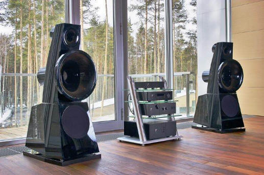
However, what it strange is that there are also some logical inconsistencies even if they did use main block as a Mid-Bass horn. Pay attention at the picture above of those black 3 ways horns or at this image:
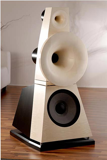
It uses at the buttom a regular sealed or ported box and the driver as direct radiator but they also put the speaker on the spikes and made the bottom looks like it is a horn output. Also at this larger model:
I have difficulties to imagine why, if the have the down-fairing horn inside, they did not use the entire footprint for the horn mouth. They have an extra foot in front and a foot on the sides. Frequency-wise it would be extra 15Hz and it would be very strange if it was no used.
I personally have a feeling that they most likely do not have anything inside going on as if it was then the shape of the block would be different and it would not be the “crack” (even decorative) between the top and bottom panels. However I do not know certainly what they did in that speaker. Rgs,
The Cat
|
|
|
|
Posted by Markus on
04-03-2007
|
Sorry if this is OT - I could start a new thread but my post is inspired by the quote below -
| drdna wrote: | | the lathe-work is rough on some of the horns. |
|
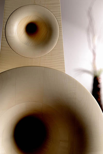
I can't decide whether that's good or bad. I'm slowly working up to getting some midrange horns. The inside finish is something I have been mulling about. Should the surface be shiny or is some roughness possibly beneficial?
B&W make use of golfball-alike dimples in their BR ports. They take advantage of little air vortices which mean that the air that is moving in and out of the port is cushioned on air and meets less resistance than in a smooth port (reducing chuffing noise) at least that's B&W's explanation, and it tallies well with what I have read about golf balls. I also remember some experiments done on aircraft hulls with a paint that gave a slight roughness (modelled on shark skin IIRC); again, a reduction in resistance was observed.
What I can't fathom yet - the sound waves in a horn have more to do with pressure variation than with air actually moving. Do the same principles apply?
|
|
|
|
Posted by Gregm on
04-03-2007
|
Romy notesQ|
It uses at the buttom a regular sealed or ported box and the driver as direct radiator but they also put the speaker on the spikes and made the bottom looks like it is a horn output. Also at this larger model |
|
On the smaller model it looks much like there's a bottom firing port -- hence the need to provide a non adjustable base (on second thought they could have disposed of the base & used the floor anyway... curious).
OTOH why have it decorative since it raises the whole speaker further off the ground and places a sitting listener smack bang facing the mid horn -- AFA I can tell from the pictures???
On the big model, how would they place a bottom firing horn with that front baffle & box design -- maybe angled (why)??? More to the point, why have a horn there: There is a big double box behind the main spkr anyway -- I assume it's used for lower freq and s/how aligned to the horns (how? dsp?).
Really we have no info on what these guys are doing -- or trying to do. Where's the dsp?
BTW, I notice the black model uses NO CABLES in the photo. Now that's a refreshing technological advance!
|
|
|
|
Posted by Gregm on
04-03-2007
|
Speculating again.
Maybe they have an extra driver firing downward that's invisible in the pictures?
|
|
|
|
Posted by Romy the Cat on
04-03-2007
|
| Markus wrote: | | Should the surface be shiny or is some roughness possibly beneficial?
B&W make use of golfball-alike dimples in their BR ports. They take advantage of little air vortices which mean that the air that is moving in and out of the port is cushioned on air and meets less resistance than in a smooth port (reducing chuffing noise) at least that's B&W's explanation, and it tallies well with what I have read about golf balls. I also remember some experiments done on aircraft hulls with a paint that gave a slight roughness (modelled on shark skin IIRC); again, a reduction in resistance was observed.
What I can't fathom yet - the sound waves in a horn have more to do with pressure variation than with air actually moving. Do the same principles apply? |
|
Markus, yes, from my point of view is that polished horns are not good. The textured surface is way more interesting, also it is not juts a surface but the density of the surface skin. The raw wood as the Odeon does is not the best way to finish horns. Since it is not the “surface” thread I would refer you to many other threads on this subject, for instance:
http://www.goodsoundclub.com/Forums/ShowPost.aspx?PostID=3710
http://www.goodsoundclub.com/Forums/ShowPost.aspx?postID=103
One more point I would like to makes: the chaoticness and randomness of horn's texture is important but the real kinky things might be accomplished buy varying the size of the texture across the horn’s bell… But it would be a subject way out of the Odeons…
Rgs, Romy the Cat
|
|
|
|
Posted by Romy the Cat on
04-03-2007
|
|
Yes, Gregm is right we have no idea what is behind the bottom “bulge” and therefore any speculation and accusation are “correct”. Nevertheless, from what I have tried, if I “design” this horn and had a desire for whatever reasons to preserve the “bulge” then I would do following:
1) Reverse positioning of HF and MF horn
2) Set this axes absolutely parallel of the upperbass horn
3) Lowpass the MF horn more aggressively, though it looks like it is low passed good enough, looking as the mouth of the HF channel.
4) Put another identical MF horns at the bottom of the upperbass horn introducing a MF only vertical MF offset
5) If do not go with MF too high (stay below 5K-6K) and if to be lucky (the distances are very important) then it would be possible to acoustically join to top MF and bottoms MD channels and to create a new virtual axis for MF the might be on the axis of the upperbass channel. Then, sine the HF horn site very close and is “in” the MF folk, the speaker might be used in more or less nearfiled application.
I have to admit that parallel vertical horns are controversial and very dangerous thing to play (all sorts of problems) but if they work then they work… Sure, the lower we do in frequency the better the vertical parallel sources work. It is the relations between a given distance and the wavelength. Still, sometimes it is possible to catch something on the murky water of self-cancellations…
The Cat
|
|