|
Posted by jessie.dazzle on
06-20-2006
|
|
I have been working on curves for tractrix horns based on data generated by HornCalc software. I configured the software to give values corresponding to radial sections for every 10mm of axial length of a horn nearly 1 meter long.
When I plot the curve, I get something that, at a glance, looks correct.
The CAD software I used to plot the actual curve (and later, to create the numerical data for the inner surface of the horn) has a feature for checking curvature continuity ; this is an evaluation tool that allows easy visualization of a curves progressive evolution… It is intended to insure accurate control of visual reflections in surfacing objects having a very high-gloss finish.
Applying the evaluation tool to the curve plotted with points every 10mm; the results indicate a somewhat non curvature-continuous curve. This is to be expected, as the curve has been generated using far too many points…91 to be precise ; each one corresponding to the 91 points supplied by the horn calculation software. For a curve like this, I would normally use something like 5 or 6 points.
Simply by reducing the points, I get better results from the evaluation tool, but still not at all what I would call good continuity.
Because visual reflections seem likely to bear some relationship to sonic reflections, I decided to perfect the curve as I would if surfacing for perfect visual reflections, while staying as close as possible to the points supplied by the horn calculation software. In the end, I was able to achieve very satisfactory results with a max of 7mm deviation from the original data (remember, this is relative to a length of nearly 1 meter).
I have included accompanying screen dumps of the process :
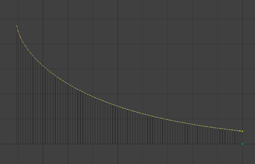
Image 1 : The curve plotted with all 91 points as given by horn calculation software
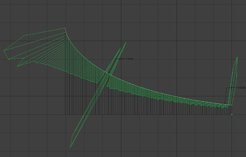
Image 2 : The same curve under evaluation
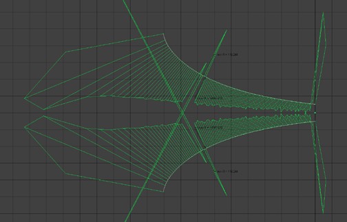
Image 3 : The same curve under evaluation ; this time mirrored
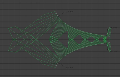
Image 4 : The same curve after having undergone a substantial reduction in the number of points (no other corrective adjustment applied)… note the kink near the mouth, and how the evaluation tool points it out with an arrow, and the accompanying suddenly much longer radiating lines… Also interesting is the inversion in the throat
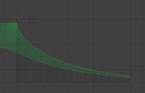
Image 5 : Same curve after some manual adjustment
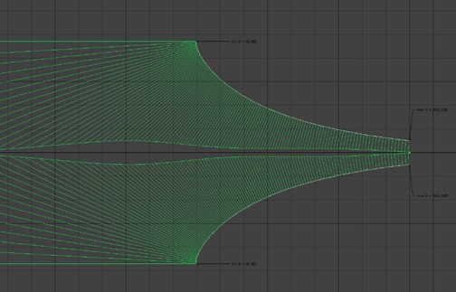
Image 6 : More manual adjustment
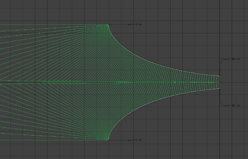
Image 7 : Final manual adjustment
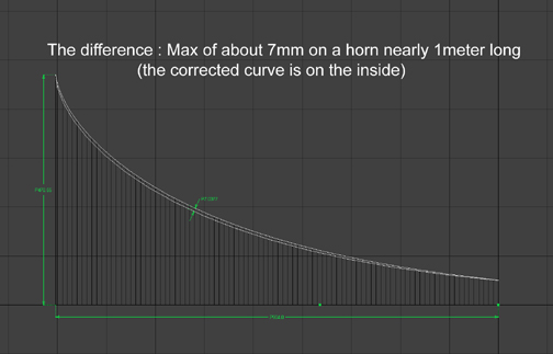
Image 8 : Comparison to the original 91 point curve
It is interesting to note that the evaluation tool shows lines radiating perpendicular to the curve at any given point, just as the sound wave is supposed to be oriented as it progresses along the horns length.
Based on these observations, I am very tempted to build the horns according to this “perfected” curve… But before I do, I would be curious to get feedback from those having more experience on the subject.
Thank you in advance,
jd*
|
|
|
|
Posted by JLH on
06-20-2006
|
 jessie.dazzle wrote: jessie.dazzle wrote: | | It is interesting to note that the evaluation tool shows lines radiating perpendicular to the curve at any given point, just as the sound wave is supposed to be oriented as it progresses along the horns length. |
|
JD,
Your attempt to perfect your horn is admirable, but in the end will not make an audible difference. You above assumption that the wave remains perpendicular is incorrect. In the perfect horn, assuming you have absolution phase and time alignment at the throat, the pressure wave front starts off as a flat plane wave. However, as the wave travels down the throat it becomes more spherical in shape; this is what the tractrix profile predicts.
The reflection points that occur in your model are of no importance. The more important shorter wavelengths will not be affected. The horn diameter, and the frequency it corresponds to, at which the reflections occur is beyond the high frequency beaming point of the horn. The frequencies that are near that point of reflection are already so long, they are acoustically invisible if the horn is properly loaded. See, once the lower frequencies are well loaded to the room, they begin to be more omni-directional and do not suffer from “line-of-sight” reflections. However, you must have a long enough horn to load your room; which in this case should be fine at 1M in length. Once energy is coupled to the room, it can break the chains of reflection.
You can build your horn anyway you want. If it makes you feel better to build the modified horn, then build the modified horn. There is such a small difference you will not be able to hear it. I would not waste time building both, just choose which one you want to build and take it easy and forget about it.
Rgs, JLH
|
|
|
|
Posted by Romy the Cat on
06-20-2006
|
|
Jessie,
I was about to replay to your post and suddenly John Hasquin posted his reply that said exactly what I meant to say. In fact he has much more credential to assess the validity of you attempts then me as he actually build the horns. In addition (surprise, surprise - a big rarity among the builders) – John actually can hear the things….
I have no reasons to question your results and I actually put your post in site’s “Knowledge Tree”. However, as a practicing person, I recognize 2 aspects that make me skeptical. Let me to name them:
1) Not necessary direct relativity of descriptive science and sonic results. You see, the scientific methods and math approximation are juts DESCRIBE the realty but they do not PRESENT it. Description of realty has one language and in many instances the language of the description takes too much over of Really. We might presume that visual reflections have own rules and evaluate the horn performance for the perspectives of those rules but who said that only those visual reflections rules are playing in the game and who know how they play? We might take an abstract theory of some kind operation that would be perfectly rational as a self-contained theory but how does is relates to a subjective perception of sound? This is a completely another question that is not implicit into the theory of that operation. So, is your profile better then the regular tractrix? I think that only way to do it is to make both of them and look at the actual sonic results. However, the second aspect might defeat it.
2) We in the horn word are in the deep dark and in the deep shit, sort of speaking… Our compression drivers are garbage that made with less precision then merchandises in “Toy’s USA”. Our horns are very poor and very irregular. Move a center of a compression driver for 1mm aside of the center of the horn and you enter the world of such a huge problems that they would be 1000000% more annoying then the issues that you described in your research. Or for instance run your driver against a distortion analyzer while you mis-centering the suspension of a diaphragm in the gap and your will see such a huge magnitude of the problem that you would loose any interest to do anything “precise” in the horn world.
I certainly do not advocate to do the things “without any rational” but in my experiments I use the “live editing techniques” that I have stolen from cinematographers. When a professions editors cuts a film then he uses many rules about duration of the screens: plot, composition, metric, rhythmic, balance, purpose of expressed or implied ideas, continuity, density, dynamics and many-many others. However, there is another methods: a person juts watches a whole film, not edited, and when he or she feel that the screens become too long then he punches a button that marks the location where "is felt” that the screen should be changed. Then, the movie is cut according those marks of the “live editing”.
So, try to do the same: make a horn, give it to another parson and ask him to talk to you from 6 feet into the horn pointed to you. Pay attention to the timbers, harmonics, contrast, accsents, articulation and so on... It is also very nice to stick a horn into your ear and juts “listen the world”.

To me, it is very illustrative test to take a horn to the roof of my downtown home and juts listed through the horn the sound of city. I usually would need 3 seconds to say that something is wrong if something was wrong…
Rgs,
Romy The caT
|
|
|
|
Posted by jessie.dazzle on
06-25-2006
|
JLH and Romy,
Thank you both for your input; I will take it all into account.
Just a bit of clarification on the curve evaluation tool I used in the images: I understand that the wavefront, ideally starts out as a plane; the form it assumes evolving to become more spherical as it progresses along the horns axis.
The evaluation tool shows lines radiating perpendicular to the horns inner wall… they are not indicative of the form of the wavefront… because they are perpendicular to the wall of the horn, they are tangent to the theoretical wave at its perimeter (I could easily crank down the sensitivity of the tool so that the lines radiate only a short distance from the horn wall).
When looked at relative to each other, the RELATIVE LENGTH of the radiating lines generated by the evaluation tool, show how the curve is evolving relative to what comes before and after a chosen point of observation along the curve… in other words, it illustrates the QUALITY OF CONTINUITY IN THE EVOLUTION. A horn that evolves in a non-continuous manner is very easily identified. Ignoring the smaller imperfections, the larger 7mm adjustment (14mm if you take it as a diameter) was necessary to correct a curve that was not evolving in a completely continuous manner.
JLH, if I understand you correctly, an adjustment of this order of magnitude is unlikely to make an audible difference (?).
I very much like the suggestion to have a person with a familiar voice speak through the horn (and yes the city has a voice… in my case, mostly 2-stroke scooters!)… sometimes I try to isolate what makes my voice recognizable to others who know me… once you remove recognizable vocabulary and speech patterns, what permits distinction between a person’s voice and a simple series of tones? Is it the little details “hanging off the edges” accompanying those tones in a combination that is a sort of code read by others?
Once again, thank you both, I very much appreciate your thoughts.
By the way… I am very very curious about the continued story regarding the fundamentals channel…
Jd*
|
|
|
|
Posted by JLH on
06-26-2006
|
| JLH, if I understand you correctly, an adjustment of this order of magnitude is unlikey to make an audible difference (?). |
|
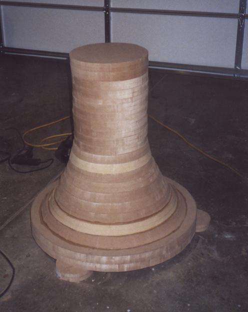
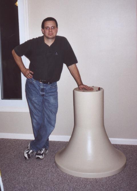
That is correct. Even when my horns were still in the rough cut stage (Not yet turned down on the lathe) it was extremely difficult to hear a difference between the rough horn and the finished horn. The sealer and paint made more of a difference than the imperfections in the unfinished horn.
IN THE ROUGH
FINISHED
Rgs, JLH
|
|
|
|
Posted by Romy the Cat on
06-26-2006
|
 JLH wrote: JLH wrote: | | Even when my horns were still in the rough cut stage (Not yet turned down on the lathe) it was extremely difficult to hear a difference between the rough horn and the finished horn. The sealer and paint made more of a difference than the imperfections in the unfinished horn. |
|
Interesting John, would it mean that it is possible to make a step-horn, similar to the profile of Central and South American pyramids? I never head a step-horn horn but it should work.
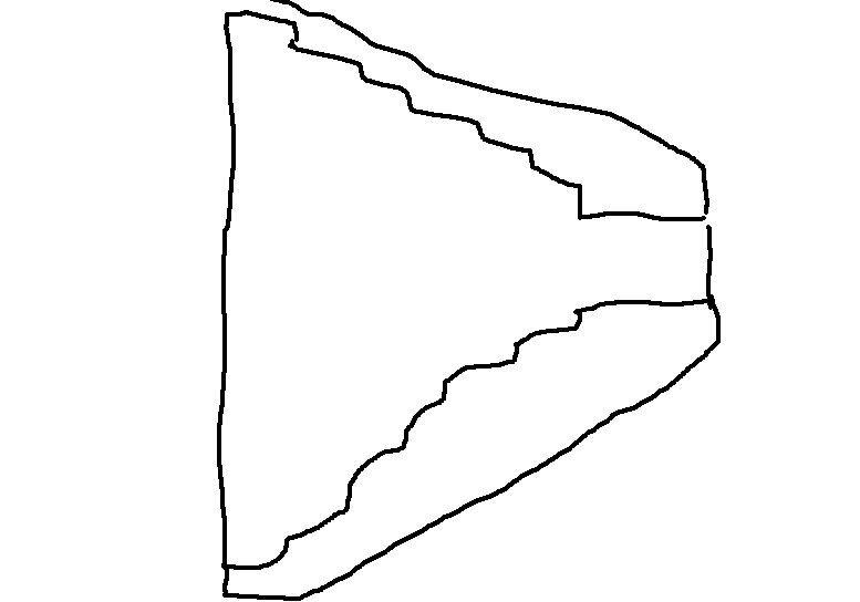
I suspect that it would not do well German, Slav or French composers but on Heitor Villa-Lobos, Alberto Ginastera or Astor Pizzolla this horn should do. :-). I’m sure it would be much more complicated to implement a properly tratrix-opening step horn then a smooth horn...
The Cat
|
|
|
|
Posted by jessie.dazzle on
06-29-2006
|
Thanks again guys,
I should be getting out of the virtual CAD horn world, and into the physical horn world for the Mid and HF horns some time very soon. The Bass horns have not yet been designed, but are going to be something like 10 feet in length (current thinking is hyperbolic-exponential; either straight down from the ceiling with a J-curve at the large end, or one large circular C-curve ... any comments?).
I will try to document the process, and consider posting the more interesting stages here on the Cat's site.
jd*
|
|
|
|
Posted by Romy the Cat on
06-29-2006
|
 jessie.dazzle wrote: jessie.dazzle wrote: | | ....but are going to be something like 10 feet in length .... I will try to document the process, and consider posting the more interesting stages here on the Cat's site. |
|
Well, Jessie.
It sounds defiantly as a very noble project. If you do wiling to document the process and post your observations during the progress then start for yourself a new thread and… God bless you. In addition to be illustrative to the horn people your thread would greatly simplify the work of your physiatrist. In the few month when you go absolutely cook-coo with your crazy idea of the 10 feet horn all that your doctor would need to do it juts look at your thread and will be able to observe all magnifications of you rolling into your insanity. :-)
I did the very same documenting my building of the late Melquiades…
BTW, the only reasons I do not do the same as you will try (45Hz straight horn with Vitavox AK151 or 15/40) is my ignorance how to resolve the time delay…
Rgs,
Romy
|
|
|
|
Posted by guy sergeant on
06-30-2006
|
Hi Romy,
How would such a time delay manifest itself in the resulting sound?
Have you had the opportunity to listen to such an attempted system?
Would the benefits of having a hornloaded AK151 not outweigh this or would it just sound too wrong to be interesting?
rgds,
Guy
|
|
|
|
Posted by Romy the Cat on
06-30-2006
|
 guy sergeant wrote: guy sergeant wrote: | | How would such a time delay manifest itself in the resulting sound? |
|
It is like driving a car where one of the wheels is larger size and rectangular.
 guy sergeant wrote: guy sergeant wrote: | | Would the benefits of having a hornloaded AK151 not outweigh this or would it just sound too wrong to be interesting? Have you had the opportunity to listen to such an attempted system? |
|
Sure I did, not with Vitavox though… OK, now pretend that this rectangular wheel is better quality and has greater traction with the road then other 3 wheels….
 Jessie wrote: Jessie wrote: | | … but are going to be something like 10 feet in length… |
|
Jessie, a few words of wisdom sort of speak if you go for you’re your 10 feet projects.
- Mass, mass, mass and mass. If your 10 feeter weights less then I would say 400 pounds then you did it wrong. The heavier is better. There are plenty of the bid wooden attempts out there but they all sound with identically – the sound of the wooden panels resonating. So, have braiceing and mass loading.
- Make the back chamber as crazy as strong as you can afford, use tank metal if you might. A 15” driver for instance in a smallish back chamber enclosure would generate a tremendous pressure. If you do wood then I would estimate that you would need at least 5”-6” of wood thickness and preferably with metal braiceing to hold this pressure properly. If I do it personally I would probably go for a concrete back chamber...
- For 10 feeter forget about the geometry of the horn. Exponential at those frequent would work as well as tratrix. Most people cheat and go for combined horns where the cure does not comply with the specific rule but follows the demander of their real-estate. It is not necessary bad as at those frequencies the room modes will severally overwrite or better to say modify what your horn will be doing.
- In the end I see 3 major problems that you will need to work with: room coupling, low pass filtering and time delay. As far as I concern all of them are quite hard to deal with. The first is might not be a problem but you will be able to assess it only AFTER you made the pair of your horns and to make any changes then will be damn costly.
Anyhow, it will be fun to watch you doing it. I very much look forward to….
Rgs,
Romy the Cat
|
|
|
|
Posted by jessie.dazzle on
07-01-2006
|
Thanks for your comments Romy.
You should like this bit of news... I forgot to mention, these will be round-section horns...
And yes, they will be very heavy... Made from a metal armature and very thick, natural (hemp) fiber-reinforced, plaster. They will be mounted on wheels. I know it sounds like adobe hut construction... and one could easily imagine a sort of DIY-looking result, but I have a lot of experience working with these materials, and though the way they look is not of primary concern, I do know how to get professional-looking results.
About the back chamber : I will of course take your advice Romy and make the thing tombstone solid and air-tight. But could you explain...
After observing a pair of AK151s operating in free air, though only lightly driven, I just don't see how they can possibly generate so much pressure, as the cone barely moves!
The sound however, even in free air, is super encouraging.
I can't get over the thickness of the cast chassis (on par with the bell housing of an Alfa Romeo 5 speed gearbox!).
As for geometry of the bass horn, I am not yet at the point of needing to define the curve ... I have smaller horns to build first. But in order to plan for room placement, and physical relationship with the smaller horns, at this point my main concern on the bass horn is the central axis;
Option "J" : Straight (vertical) for most of the length, curving 90° before the mouth.
Option "C" : One big continuous curve (a sort of mega "Horn of Plenty").
As the C curve has a less sharp bend, that to me seems the better choice... but it does take more space.
Low Pass Filtering : I am certainly ignorant here (an advantage when undertaking major projects... otherwise I probably would not be attempting any of this), as I don't see the problem... I had simply planned to use a large induction coil with each AK151. ???
Time delay : Um yes... This to me seems the most threatening issue... But as I mentioned, these horns will be on wheels, free to move independently of the other horns. However, my room may not be large enough to accommodate the necessary staggering. This could lead to a near-field listening situation that would be out of scale with the horns. Which could in turn lead to me looking for another house.
Thanks again,
jd*
|
|
|
|
Posted by Romy the Cat on
07-01-2006
|
 jessie.dazzle wrote: jessie.dazzle wrote: | | After observing a pair of AK151s operating in free air, though only lightly driven, I just don't see how they can possibly generate so much pressure, as the cone barely moves! |
|
Why shout they move? One of the idea of using horn is minimize excursion of the diaphragm and let it do not move a lot. Still it might be possible le that this Vitavox will not be the best chose for your horn, with LF horns you never know. It all depends what kind horn you will be making and how are you planning to use it. Even then Sound of this thing might not be predicted and should be observed after everything is gone….
 jessie.dazzle wrote: jessie.dazzle wrote: | | As for geometry of the bass horn, I am not yet at the point of needing to define the curve ... I have smaller horns to build first. But in order to plan for room placement, and physical relationship with the smaller horns, at this point my main concern on the bass horn is the central axis;
Option "J" : Straight (vertical) for most of the length, curving 90° before the mouth.
Option "C" : One big continuous curve (a sort of mega "Horn of Plenty").
As the C curve has a less sharp bend, that to me seems the better choice... but it does take more space. |
|
I think J-horn is more practical as it has smaller footprint. It looks like one single J0curve does not create a lot of problems sonically. Still you are entering a railm where no one can say anything defiantly. Sill if I had space I would go for a straight horn. If your real-estate can afford C-horn then you can afford a straight horn…
 jessie.dazzle wrote: jessie.dazzle wrote: | | Low Pass Filtering : I am certainly ignorant here (an advantage when undertaking major projects... otherwise I probably would not be attempting any of this), as I don't see the problem... I had simply planned to use a large induction coil with each AK151. ??? |
|
Yesm I know but there is a catch in there. Those drivers: 515G, AK151, AK15/40, D130 and alike do reproduce some HF over 300Hz. The problem that it is not good sounding HF and it might screw up your lover MF solution. So, to resolve it you might need to go for second order. Religiously speaking the second order is not good but it might be the only solution. If you go for smaller drivers size (10”, 12” or 14”) then the problem would be even more. If your horn was 40Hz horn and you would like to kill it at 120Hz then you need even sharper slope. Once again you need to put this thing in use in order to say anything. It is possible that some drivers, in some application might be working fine “together”, handling the same frequency range with both channels. I have seen those satiations and did use them myself.
 jessie.dazzle wrote: jessie.dazzle wrote: | | Time delay : Um yes... This to me seems the most threatening issue... But as I mentioned, these horns will be on wheels, free to move independently of the other horns. However, my room may not be large enough to accommodate the necessary staggering. This could lead to a near-field listening situation that would be out of scale with the horns. |
|
Welcome to the club. In the near-field environment the time dealt from 10” horn is a mortal issue. People out there use digital time delays for the rest spectrum and try to convince themselves that it sounds acceptable. I despise those efforts and generally do not even go to listing horns with digital delays (uselessly they use digital crossovers as well). My observation is that those horn installations with digital delays/crossovers sound extremely poor. I know, I know there is an army of D-horn people that disagree with me but I feel that they hardly know what they talk/hear… There is another option. Last year, or even before, when I was bitching to Dima about the very same subject he proposed a time delay processor that would do the delay “differently”. He meant to do it without digitalizing of sound, using modulation and de-modulation, storing the UHF signal at temporary memory. The idea looks very-very promising and Dima proposed to make a prototype to try it’s transparency. At this point I do not know how acceptable it might be. If it was then the FM delay processor might be available from Dima.
 jessie.dazzle wrote: jessie.dazzle wrote: | | Which could in turn lead to me looking for another house. |
|
Here we do… Still, even with a large room 10” is hardly manageable. Let pretend that your horn has 60” by 70” mouth. With 10ms delay and J-horn you would need to position the J-horn way ahead of your MF/HF horns but with suck a large mouth you would find yourself on deep reflections. Long time ago I come up with a scenario how I would like to do it if I go for 50Hz straight horn but I have no real estate for it. Here is how I thought to make it:
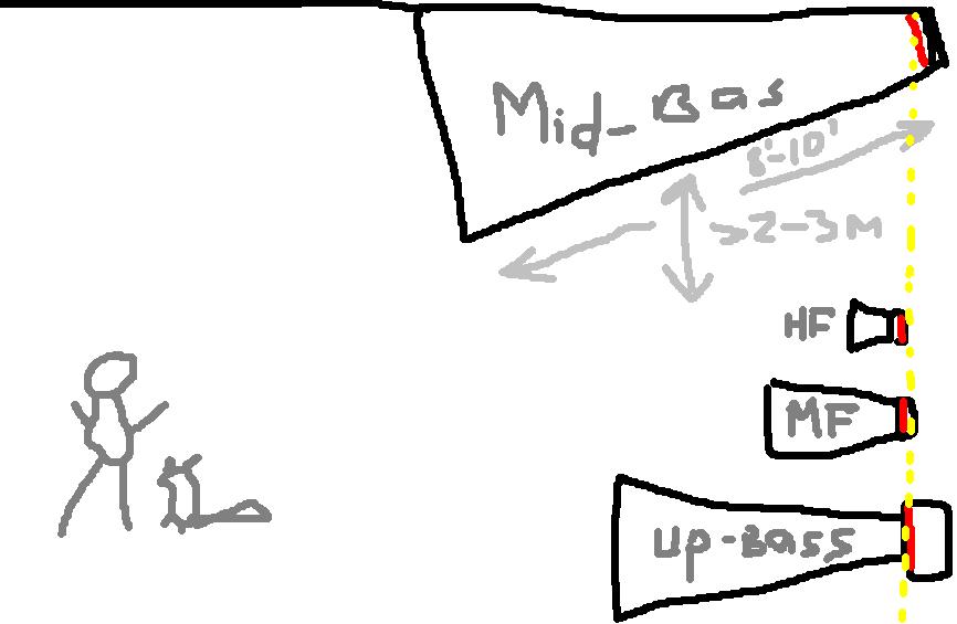
Until I have the correct room my drivers sit in my storage….
Rgs,
Romy the Cat
|
|
|
|
Posted by jessie.dazzle on
07-01-2006
|
Romy,
As always, thanks for your thoughts.
Regarding cone movement versus rear chamber pressure : I understand that low excursion explains to a great extent, the advantages of horn-loaded designs, I just don't understand how something that "does not move", can generate such pressure... I realize that this is taking place within a constrained volume, but still... Can a bird fly without flapping its wings?
Regarding J-Axis : The floor space in my room, though somewhat generous by Eruopean standards, it is still not huge, which presents a good argument for the J-Axis design... I have built computer models of horns using an inverted J-Axis, placing the mouth up high, just as you have shown in your drawing. This orientation places the driver on the floor, leaving some space down low for other horns. However, in my case, because the ceiling is 5 meters high, a bass horn with the mouth up high would be radiating into half space... the solid condrete walls would be closer.
The inverted J solution may require aiming the mouth down a bit (again, just as your drawing shows), due to lack of distance between the horns and the listening position.
(BTW, have you tried aiming your Fundamentals Channel horn down towards your listening position?)
The other option would be to take advantage of the high ceiling, and hang a pair of straight horns from the ceiling, aimed straight down at the listening postition... I have no idea what result such a set up might yield.
To be continued...
jd*
|
|
|
|
Posted by Romy the Cat on
07-01-2006
|
 jessie.dazzle wrote: jessie.dazzle wrote: | | Regarding cone movement versus rear chamber pressure : I understand that low excursion explains to a great extent, the advantages of horn-loaded designs, I just don't understand how something that "does not move", can generate such pressure... I realize that this is taking place within a constrained volume, but still... Can a bird fly without flapping its wings? |
|
Hm, what you worry, Jessie, the acoustic pressure or visible movement of the cone? If the driver generates a necessary acoustic pressure at given frequency then why you worry that it does not extend far geometrically? Many good high sensitivity drivers have hard sustention and do not shake like the contemporary shity drivers (look what Kaharm’s ceramic driver do – it is scare even to look at them). St Do not forget that all of those drivers were made to work WITH horns and they presume that the driver will have extra 6-9dB gain from the horn.
 jessie.dazzle wrote: jessie.dazzle wrote: | | The inverted J solution may require aiming the mouth down a bit (again, just as your drawing shows), due to lack of distance between the horns and the listening position. |
|
Yes, I understand, Still do not forget that if you have 40hz-50Hz horn and if it does NOT go too high then it is fine to turn it outside a little
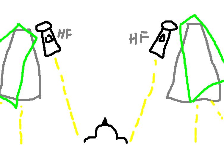
 jessie.dazzle wrote: jessie.dazzle wrote: | | (BTW, have you tried aiming your Fundamentals Channel horn down towards your listening position?) |
|
Nope, I did not get my 250Hz yet, hopefully in a week.
 jessie.dazzle wrote: jessie.dazzle wrote: | | The other option would be to take advantage of the high ceiling, and hang a pair of straight horns from the ceiling, aimed straight down at the listening postition... I have no idea what result such a set up might yield. |
|
Well, I do not think that there is such a thing as “aimed straight” at 50Hz. At 50Hz we do not aimed anything but rather load room with specific frequency. If you point your mid-bass channel “straight down” then the mouth of your horn will be way from the room boundaries and will be deep in the mid of the room. This might create two problems. Firsts, you might loose ~10-25Hz in response as the boundaries of your room will not “help” you. Second, if the source of your radiation in the mid of the room than you might have near-equal distances from the top and bottom boundaries. This would be a perfect recipe for the standing-waves.
The Cat
|
|
|
|
Posted by jessie.dazzle on
09-12-2006
|
It is looking like I will be constructing the 45Hz horn before some of the others. In considering time-alignment I went back through some of our posts and found this :
Quote from Romy : "...There is another option. Last year, or even before, when I was bitching to Dima about the very same subject he proposed a time delay processor that would do the delay “differently”. He meant to do it without digitalizing of sound, using modulation and de-modulation, storing the UHF signal at temporary memory. The idea looks very-very promising and Dima proposed to make a prototype to try it’s transparency. At this point I do not know how acceptable it might be. If it was then the FM delay processor might be available from Dima.
Has the Dima made any progress on this project ?
In your drawing showing the ceiling-mounted bass horn, is it not a problem that the distance from the listener to the bass driver would be greater than the distance from listener to the drivers of the HF/MF horns (because you are measuring on a diagonal it must be greater)... Or is it the distance between the listener and the MOUTH of the horn that is important ?
Regards,
jd*
|
|
|
|
Posted by Romy the Cat on
09-12-2006
|
|
The Dima’s idea of delaying the modulated signal still not in the auditable format. As I understand he designed the circuit and we get all parts we need but it moves forwards slow. The devise will have modulator, delay mechanism, demodulator and output buffer. Since I would not accept as “success” anything besides the absolute transparency and absolute not-audibility and since there is no absolutely transparent line-level output buffer out there beside the Guy Hammel buffer I was initially planning to use the Placette’s output stage for the delay. I spoke with Guy and he was agreeing to supply one. However, Dima suggested that he might come up with “absolutely transparent buffer” himself. He did designe and built the buffer and now it is sitting in his place, waiting to be shipped. If the buffer turned out to be transparent then it might be a good start for the delay circuit. If the buffer will not be transparent then there is no reason to pursuit with the delay implementation.
Anyhow, the distance between the listener and the MOUTH of the horn is irrelevant (at least for time aliment). The distance between the listener and the cone of the driver is one that counts.
Rgs,
Romy the Cat
|
|
|
|
Posted by deemon on
09-12-2006
|
Yes , the idea of time delay machine is completely clear now . I made some experiments with analog and digital parts of the circuit , ewerything OK , and I need to assemble all the parts together , but now I am finishing the new hybrid class A amp - Zarathustra II , it's a big work and I cannot make two projects simultaneously , it's a pity . After finishing the amp I will finish this delay block too , but before it Roma will test my new line level buffer . If the buffer won't be transparent enough - I must redesign it . In my system is seems to be transparent .....
Best regards
Dima
|
|
|
|
Posted by jessie.dazzle on
09-14-2006
|
Romy and Dima,
Thanks for the update on the delayed Time Delay research. I sincerely hope the device performs to your expectations.
I will follow your progress with self-centered interest, because in my case, the best scenario still puts the bass drivers at a greater distance from the listening point than is the case with the the other drivers. The difference is not huge, but I could most likely benefit from such an invention should you decide to make it (or the plans to build it) available.
Meanwhile, I wish you much success with the Zarathustra II !
jd*
|
|