|
fiogf49gjkf0d
I have no doubts that it will work but I would like to understand HOW it works.
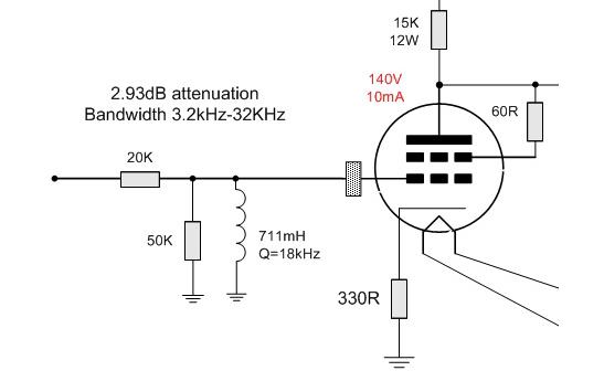
The objective it to have first order filter, of cause not the filter where capacitance do high-pass roll off but RL. In RL filter there is not reactive elements in series pass and the rolling off inductance acts as a subtractive filter with no band-pass or slope pass coming through the reactive chain of filter. Anyhow who has ears and even a remote residue of listening consciousness would easily recognize the sonic advantage of RL in THIS situation.
However, I need to drop some voltage coming to the grid of the tube and my driver stage has a not a lot of power. So, I have the RL filter combined with voltage divider. Here where I have some confusion. Would the presents of voltage divider convert my pure first order RL filter into some kind sharper filter, let call it 1.5 order filter? Let me to explain how I think and explain me why I am wrong.

The AC above 3.2kHz flows over the series resistor. Everybody is happy; the impedance of the shunted coil is too high and the AC does not “see” the filter. The only shuntable element in the circuit is 50K resistor to the ground that does the role of voltage deviser. Well, in realty the coil impedance of coil while the filter in band-pass of course is in the play as well but this “band-pass impedance” is calculated into the value of the coil.
Now, the frequency of the signal is dropping. The impedance of the coil begin to drop at lower frequencies and some of the AC signal flows to ground performing the frequencies-depending attenuation otherwise known as filtration. However, in parallel to the dropping impedance of the coil there is a bottom part of the voltage divider. The coil’s impedance and the parallel resistor’s impedance accelerate the combine impedance drop, making the filter to roll off shaper then 6dB per octave. Is it correct vision or it is just my inflated imagination?
If I am right then it order to maintain the 6dB and Bessel curve at first order I would need gradually to increase the impedance of the parallel resistor of the divider. I wonder according to what mechanism I can do it in order to avoid co complicated active mechanism of monitoring and correcting the rate of impedance dropping. Rgs, Romy the Cat
|